


www.petsafe.net 7
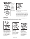
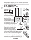
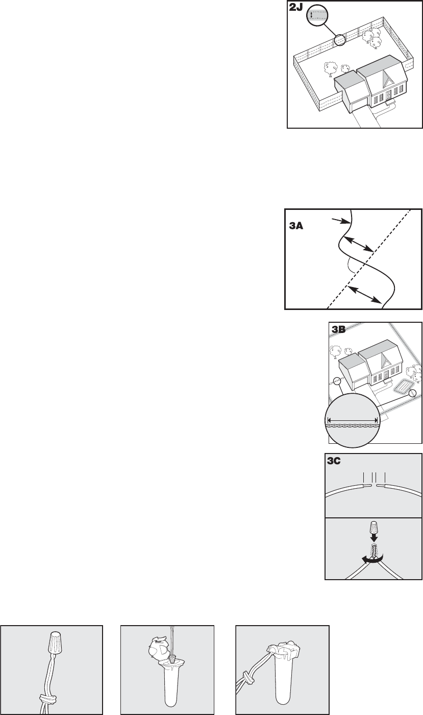
Sample 6 (2J): Wire Loop Attached to Existing Fence (Double Loop)
This layout allows you to include your existing fence as part of your layout and
keep your pet from jumping out or digging under your existing fence. It reduces
the amount of wire which will need to be buried. Run the wire from the Fence
Transmitter to A, A to B, B to C, C to D, D to E, E to F, make a U-turn and
follow your path all the way back to A,
keeping the wire separated 3 to 5 feet. Twist
the wire from A back to the Fence Transmitter. See the “Install the Boundary Wire”
section for more information on attaching the wire to a fence.
3-5'
E
F
B
A
D
C
__________________________________________________
Position the Boundary Wire
Lay out the Boundary Wire using your planned boundary and test the system BEFORE burying the wire
or attaching it to an existing fence. This will make any layout changes easier. Work carefully. A nick in the
wire insulation can diminish the signal strength and create a weak area where your pet can escape.
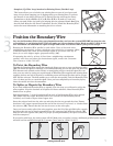
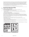
Running the Boundary Wire parallel to and within 5 feet of electrical wires,
neighboring containment systems, telephone wires, television or antenna cables,
or satellite dishes may cause an inconsistent signal. If you must cross any of
these, do so at 90-degree angles (perpendicularly) (3A).
If separating the wire by at least 10 feet from a neighboring containment
system’s wire does not reduce the inconsistent signal, contact the Customer
Care Center at 1-800-732-2677.
To Twist the Boundary Wire
Boundary Wire
10’
10’
Buried Cable
90˚
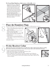
Twisting the Boundary Wire cancels the signal and allows your pet to cross over that area safely
(3B). To ensure the signal is cancelled, it is recommended that you cut and splice the Boundary
Wire between each twisted section. Plastic or metal piping will not cancel the signal. You can
twist your own wire by cutting two equal lengths of Boundary Wire supplied and twisting them
together. Anchor one end of the wires to something secure and insert the other end in a power
drill. Pull the wire taut. The drill enables you to twist the wire quickly. Twist the Boundary Wire
10 to 12 times per foot to cancel the signal. Once you have completed your boundary layout,
insert the twisted wire into the transmitter.
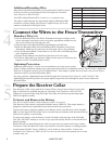
To Splice or Repair the Boundary Wire
If you need additional Boundary Wire to expand your wire loop, you will need to splice the
wires together. Note the locations of all splices for future reference. Most Boundary Wire
breaks occur at splices.
Strip approximately
3
⁄8 inch of insulation off the ends of the Boundary Wires to be spliced
(3C). Make sure the copper Boundary Wire is not corroded. If the Boundary Wire is
corroded, cut it back to expose clean copper wire.
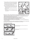
Insert the stripped ends into the wire nut and twist the wire nut around the wires. Ensure
that there is no copper exposed beyond the end of the wire nut. Tie a knot 3 to 4 inches from
the wire nut (3D). Ensure that the wire nut is secure on the wire splice.
Once you have securely spliced the wires together, open the lid of the gel-fi lled splice capsule
and insert the wire nut as deeply as possible into the waterproof gel inside the capsule (3E).
Snap the lid of the capsule shut (3F). For proper system performance, the splice connection
must be waterproof.
10
T
wists/ft.
1
3/8"
3/8"
2
If your splice pulls loose, the entire system will fail. Make sure your splice is secure. Additional gel-fi lled splice capsules
and wire nuts are available through the Customer Care Center at 1-800-732-2677.
3D
3E
3F
Step
3