


36
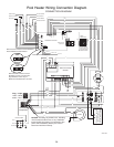
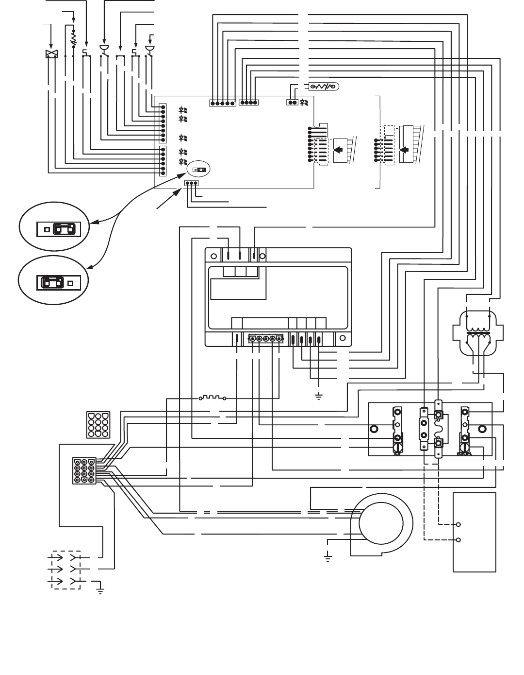
Pool Heater Wiring Connection Diagram
Plug –12 pin
120V – Black
240V – Red
JMP
9
1
J6
JMP
1
JMP
1
External Control Interface Circuit Disabled,
Heater Membrane Pad Enabled
External Control Interface Circuit
Enabled, "Pool On" and "Spa On"
Keys Disabled. "OFF" Key on
Membrane Pad Remains Functional
.
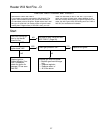
CONNECTION DIAGRAM
AGS Switch
Stack Flue Sensor
Gas Valve
Air Flow Switch
Extra Switch 1
Hi-Limit Switch
Pressure Switch
VAL
TH
IND
GND
24VAC
24VAC
FS
THERMISTOR
OPERATING CONTROL
1
PS
HLS
ES1
AFS
AGS
SFS
GAS
MEMBRANE PAD
CONNECTION
Spa Line
Common Line
Pool Line
IGNITION CONTROL
MODULE
DIAGNOSTIC INDI CATOR
F1 F2
24
VAC
S1
240
S1/
120
L1
L1
L2
BM
FL
F1
L2
S2
TH IND
VALGND
GND
GND
BLOWER
Line 2
120VAC
IGNITER
TRANS
Line 1
Ground
JUNCTION BOX
F
I
R
E
M
A
N
S
S
W
I
T
C
H
Repla ce jum per with
leads to Fireman' s
Swi tch (field installed) .
24VAC
SEC
Y/W
Y/W
Y/R
Y/O
Y/BL
O
W
W
BK
BK
O
GY
GY
BK
BK
R
Y
BK
W
BL
Y
BK
W
BL
GY
GY
GY
GY
BK
BK
W
RRW
G
Y
R
R
Y
YY
W
BK
Y/W
W
W
R
R
BL
BL
O
O
O
O
PR
PR
Y/R
Y/BL
Y/O
Y/W
Y
Y
Y
Y
Y
Y
Y
YYY
BR
BR
3661 0200
External Control Interface
Y
NOTICE: Touching any 24VAC wire, including
the Fireman's Switch wire, to any 120/240V
terminal while the heater is connected to line
power will immediately destroy the control
board and void the warranty.
BK
R
GND
G
12 Position
Receptacle
1
NA/LP
Models Only
Y/R
Y/BL
Y/O
Y/W
NA/LP Models:
J6 incl. pins 1-6;
Connect 9-Wire
Cable as show
n
6
1
J6