


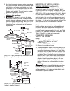
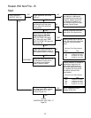
Connect the L1 of the power supply to the black wire,
the L2 or neutral lead to the red wire, and the ground
wire to the green wire.
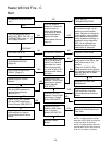
A time clock controlling the filter pump should have a
low-voltage Fireman’s Switch that switches off the heater
at least 15 minutes before shutting off the pump.
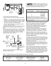
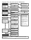
FIREMAN’S SWITCH CONNECTION
NOTICE: If, while there is line voltage connected to the
heater, you touch either line voltage terminal with any
24VAC wire that is connected to the control board
(including the Fireman’s Switch jumper), you will immedi-
ately destroy the control board and void the warranty.
NOTICE: When using a timer and Fireman’s Switch, the
heater’s power supply should come from the load side of
the timer. The Fireman’s Switch completes the circuit for
the low voltage safety switches. It DOES NOT get any
line voltage power from the power supply.
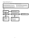
Connect the Fireman’s switch to the heater as follows:
1. Switch off power to heater at main circuit breaker
panel.
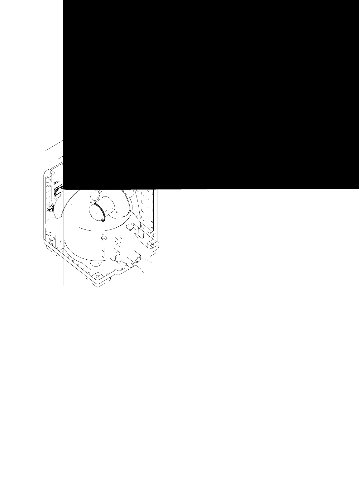
2. Unbolt and remove the access door panels (see
Figure 3, Page 5).
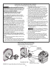
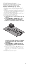
3. Open control box cover (see Figure 22).
4. Remove the factory-installed jumper between the
Fireman’s Switch terminals (see Figure 23).
5. Connect the wires between the Fireman’s Switch ter-
minals on the heater and those on the time clock
using 18 gauge wire with a minimum 3/64" (1.2mm)
thick insulation rated for a temperature rise of at
least 105°C. Route the wires out through the knock-
out on the bottom of the Control Box. Use a 90° con-
duit elbow and conduit run out through the cutout on
the Lower Enclosure, next to the Junction Box.
21