


Install a check valve to prevent back-siphoning through
the heater when the pump is off.
NOTICE: Improper operation of chemical feeders can
cause severe damage to the heater which is not covered
by the warranty. Install the chemical feeder downstream of
the heater (see “Water Chemistry,” below).
Install a chemical resistant one-way check valve
between the heater and the chemical feeder.
NOTICE: If you install a chemical feeder and check valve,
you must install a relief valve on the heater. See “Pressure
Relief Valve”, Page 18.
NOTICE: If the heater is plumbed in backwards, it will
cycle continuously. Make sure piping from filter is not
reversed when installing heater.
WATER PIPING
Connect the heater directly to 2" PVC pipe, using the
integral unions provided. Heat sinks are not required. The
low thermal mass of the heater will prevent overheating
of the piping connected to the pump even if the heater
shuts down unexpectedly.
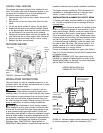
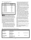
WATER FLOW RATE
Maximum and minimum water flow rates required by the
heater are listed below:
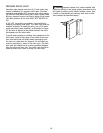
If the water flow rate to the heater is above 120 GPM (454
LPM), it must be reduced by installing a manual bypass
valve (Figure 16). After installing the valve, adjust the valve
to bring the flow rate within the acceptable range. Then
remove the valve handle or lock it in place to prevent tam-
pering.
Occasionally a two-speed pump will not develop enough
pressure on the low speed to operate the heater. In this
case, run the pump at high speed only to operate the
heater. If this does not solve the problem, do not try to
run the heater. Instead, correct the installation.
Do not operate the heater while an automatic pool clean-
er is also operating. If the circulation pump suction is
plugged (for example by leaves), there may not be ade-
quate flow to the heater. Do not rely on the pressure
switch in this case.
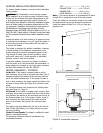
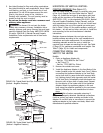
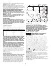
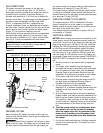
WATER CHEMISTRY
Water chemistry should follow good swimming pool water
chemistry practices. See Table 9 (page 17) for water
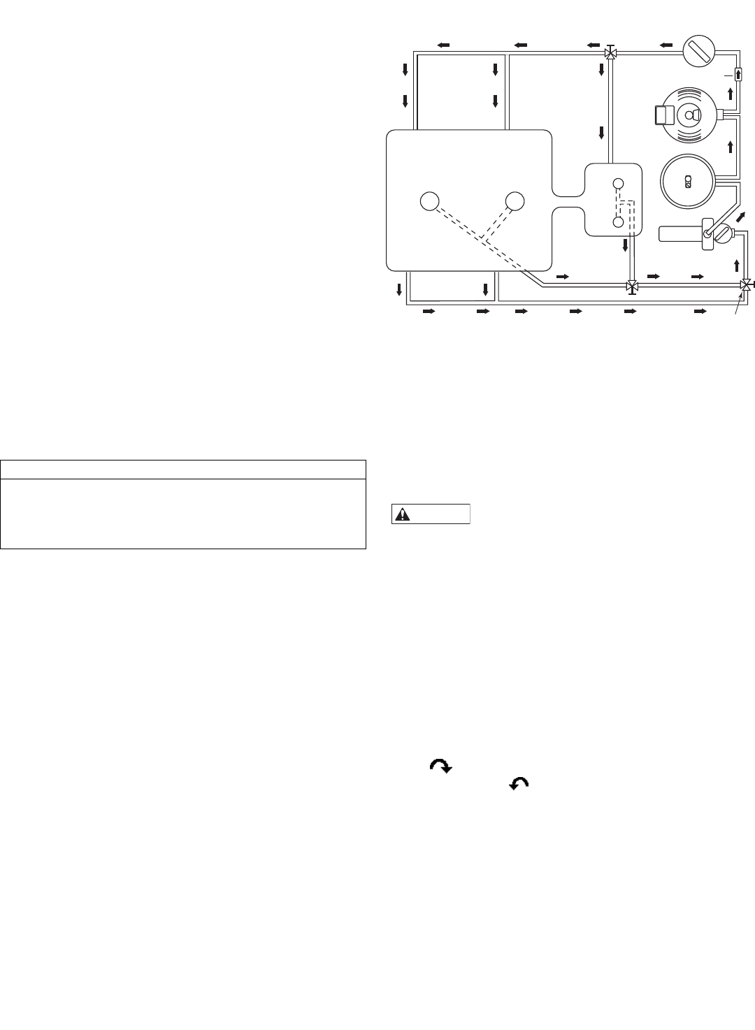
chemistry parameters. When using a chlorinator, install it
downstream from the heater and at a lower level than
the heater outlet. Install a corrosion resistant positive
seal Check Valve (see Figure 15) between the heater
and the chlorinator to prevent concentrated chemicals
from back-siphoning into the heater. Back-siphoning is
most likely to occur when the pump stops, creating a
pressure-suction differential. Do NOT sanitize the pool by
putting chlorine tablets or sticks into the skimmer(s).
When the pump is off, this will cause a high concentration
of chlorine to enter the heater, which could cause corro-
sion damage to the heat exchanger.
WATER PRESSURE SWITCH
Hazardous pressure. Do not bypass the
Water Pressure Switch or render it inoperable.
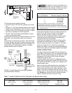
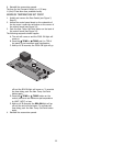
Switch Settings
The water pressure switch turns off the burner if the
water flow is interrupted. If the water flow is restricted,
the water pressure switch may prevent the burner from
firing and cause the “Service System” light to go on. If
the light remains on after the filter has been serviced,
have a qualified service technician check the system.
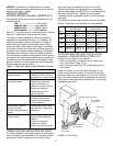
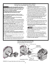
For deck-level heater installations, the Pressure Switch is
factory set at 3 psi (20.6 kPa). If the pressure switch is
one to two feet (.3-.6M) below or one to five feet (.3-
1.5M) above the pool water level, reset the switch so
that it is open when the pump is off and closed when the
pump is running. Turn the star-wheel on the switch clock-
wise ( ) to raise setting (heater below the pool) and
counterclockwise ( ) to lower the setting (heater
above the pool – see Figures 17 and 18). Test the switch
after resetting.
NOTICE: When the heater is mounted more than five
feet (1.5M) above or two feet (.6M) below the deck level,
a Pressure Switch is no longer adequate. A Flow Switch
must be installed instead.
NOTICE: Heater operation with incorrect Pressure Switch
setting may cause operation with no water flow.
Operation of the heater without sufficient water flow may
severely damage it.
WARNING
16
Model Minimum Flow Maximum Flow
200 20 (76) 120 (454)
250 25 (95) 120 (454)
300 30 (114) 120 (454)
400 40 (152) 120 (454)
Pool
Main
Drain
Spa
From Pool
3-Way
Valve
3-Way
Valve
3-Way
Valve
Chlorinator
Heater
Filter
Pump
Check valve
FIGURE 15: Typical pool piping layout
Table 8: Maximum and Minimum Flow Rate in GPM (LPM)