


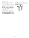
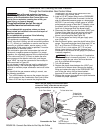
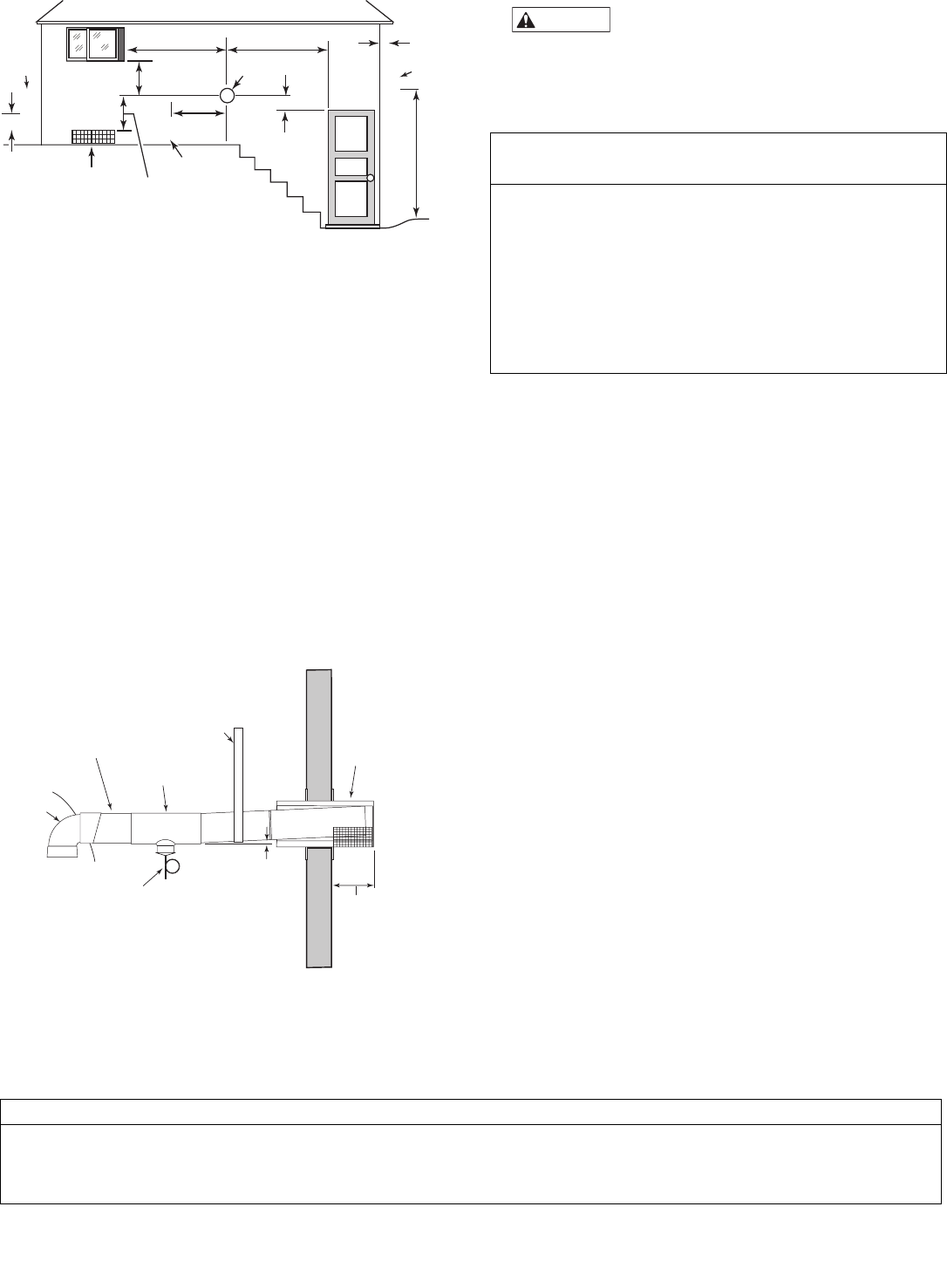
The terminal must be located (Canada):
• at least 10 feet (3.3M) from any opening into a build-
ing.
• at least 12" (.3M) above finished grade or the normally
expected snow accumulation level, whichever is higher
• At least 4 feet (1.2M) horizontally from electric meters,
gas meters, regulators and relief equipment
• At least 7 feet (2.1M) above grade adjacent to walk-
ways or similar traffic areas.
Allow at least three feet (1M) vertical clearance over vent
termination when terminating under an overhang or
deck.
Avoid corners or alcoves where snow or wind could have
an effect. Exhaust may affect shrubbery and some build-
ing materials. Keep shrubbery away from termination. To
prevent staining or deterioration, sealing or shielding
exposed surfaces may be required.
8. Fire Hazard. Do not run the heater vent
into a common vent with any other appliance. Do not run
the Special Gas Vent into, through, or within any active
vent such as a factory built or masonry chimney.
Final Installation Check
Check that horizontal vent pipe runs slope uniformly at
least 1/4" per foot (2cm per meter) to condensate
drain(s). No sags, no dips, no high or low spots.
Check that vent is supported at elbows, tees, and hori-
zontal and vertical runs according to manufacturer’s
instructions and code requirements.
Check that vent supports and wall and ceiling penetra-
tions allow free movements up, down, and sideways
without putting any strains on the heater or vent body.
Check for at least six inch (15cm) free air clearance
between the heater vent pipe and combustible materials.
Check that all joints are completely together and sealed.
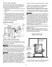
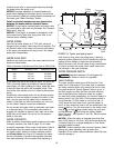
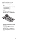
WATER CONNECTIONS
The heater requires proper water flow and pressure for
its operation. See Figures 15 for the recommended instal-
lation. The filter pump discharges to the filter, the filter
discharges to the heater, and the heater discharges
directly to the pool or spa.
A manual bypass valve should be installed across the
heater when the pump flow exceeds 120 GPM (454 LPM).
See “WATER FLOW RATE” on page 16 for setting of the
manual bypass valve.
Make sure that the outlet plumbing from the heater con-
tains no shut-off valves or other flow restrictions that
could prevent flow through the heater (except as noted
below). To switch flow between the pool and spa, use a
diverter valve. Do not use any valve that can shut off the
flow. Do not use a shut-off valve to isolate the heater
unless it is below the level of the pool or spa.
WARNIN
G
15
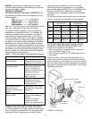
Vent Brand Wall Thimble Horizontal Terminal Vertical Terminal
Saf-T Vent
®
(Part of Vent term.) 5490CI Horizontal Term. 5400 Cap
Saf-T CI Vent
®
(Part of Vent term.) 5490CI Horizontal Term. 5400 Cap
Z-Vent 2SVSWTF04 2SVSTTF04 Tee 2SVSRCF04 Cap
Table 7: Listed Thimbles and Vent Terminals (for Special Gas Vents)
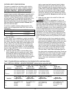
4" Special Gas Vent (Vertical or Horizontal)*
No. of 90° Elbows Maximum Length in Feet (M)
0 70 ft. (21.3M)
1 57 ft. (17.4M)
2 45 ft. (13.7M)
3 32 ft. (9.8M)
4 20 ft. (6.1M)
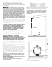
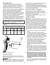
* Minimum vent length is one foot (.34M), or in accordance with
vent manufacturer’s instructions, and local and national codes.
Horizontal vents 3’ (1M) or less in length do not require a condensate
tee, but must slope down toward the outlet at 1/4” to the foot (2cm/M) to
allow condensate to drain.
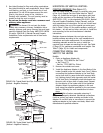
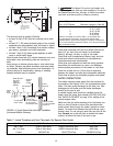
3" (7.6 cm) Min.,
12" (30.5 cm)Max.
Clearanc
e
Condensate
drain w/Trap
Condensate
Tee
Support
weight
of pipe
Listed
Termina
l
Metal Special
Gas Vent
requires
Appliance
Adapter
Metal
Vent
Body
Slope at least
1/4" per foot
(2 cm per Meter)
down towards
condensate drain
FIGURE 14: Typical Special Gas Vent Pipe Installation
(Horizontal-Positive Pressure)
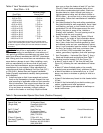
1' Min.
4' Min.4' Min.
4' Min.
4' Min.
3' Minimum clearance if
horizontal distance to
exhaust opening is less
than 10 feet.
Forced Air
Inlet