


20
GAS CONNECTIONS
The heater requires a gas supply of not less than
4" (10.2cm) wc and not more than 14" (35.6cm) wc.
Gas supply pressures outside of this range may result in
improper burner operation. A minimum flowing or
dynamic inlet pressure of 4" (10.2cm) wc is required to
maintain input rating. The gas supply must be installed in
accordance with the National Fuel Gas Code, ANSI
Z223.1, or standard CSA B149.1, Natural Gas and
Propane Installation Codes, as applicable and all applica-
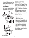
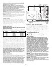
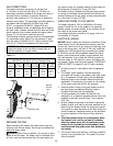
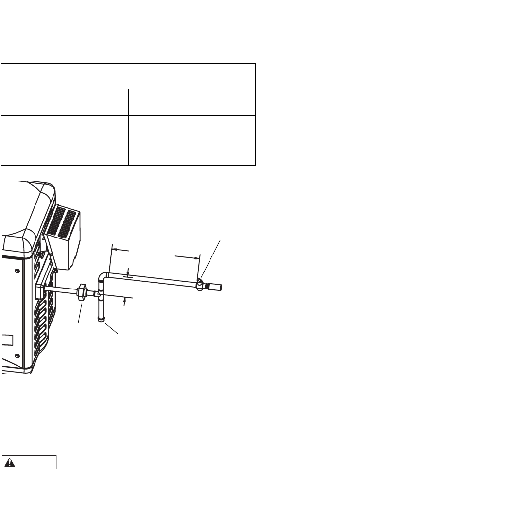
ble local codes. Install a manual shut-off valve and a sed-
iment trap and union located outside the heater panels
(Figure 21). Do not use a restrictive gas cock.
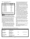
The following minimum gas pipe sizes are recommended
for natural gas supply piping. For low pressure LP gas,
pipe size may be reduced by 1/4", with a minimum pipe
size of 3/4". Check for compliance with local codes.
NOTICE: DO NOT use a corrugated flexible gas line to
supply the heater. it will not deliver enough gas (at
nominal diameter) to supply heater.
PRESSURE TESTING
Before operating the heater, the heater and its gas con-
nections must be leak tested. Test all gas connections for
leaks with soapy water.
Risk of fire or explosion. Do not use an open
flame to test for leaks. The heater and its individual shut-
off valve must be disconnected from the gas supply pip-
ing system during any pressure testing of that system at
test pressures in excess of 1/2 psig (3.5 kPa).
The heater must be isolated from the gas supply system
by closing its individual manual shutoff valve during any
pressure testing of the gas supply at test pressures equal
to or less than 1/2 psig (3.5 kPa).
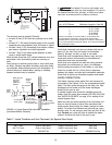
SUPPLYING POWER TO THE HEATER
The heater requires a 120V or 240V/60Hz/1Ph power
supply. Enclose the line to the heater in an approved
flexible conduit connected directly to the junction box on
the inside of the access door panel.
Line voltage field wiring should be 14 gauge, with a cir-
cuit capacity of 15 amps.
ELECTRICAL WIRING
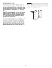
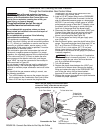
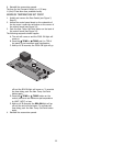
NOTICE: Before making any electrical connections to the
power supply, remove the access door panels, open the
control box, remove the 12-pin plugs from their bag, and
plug in the correct plug (120 volt or 240 volt). Note that
installing the 120V plug and then connecting the heater
to 240V line current will immediately destroy the trans-
former, control board and ignition control module, and
will void warranty. If you install the 240V plug and con-
nect the heater to 120 volts line current, the heater will
not operate. Please read the boxes headed “IMPORTANT!
READ ME FIRST!” on pages 23 and 27 before proceed-
ing.
1. All wiring must be in accordance with all applicable
codes.
2. The heater, when installed, must be electrically
grounded and bonded in accordance with local codes
or, in the absence of local codes, with the National
Electrical Code or the Canadian Electrical Code (as
applicable). A bonding lug is provided on the outside
of the panel under the vent for this purpose.
3. Electrical power circuits to the pool heater must fol-
low local codes and National Electrical Code or
Canadian Electrical Code (as applicable).
4. All wiring between the heater and devices not
attached to it, or between separate devices which are
installed in the field, must be Type T wire rated for
35°C rise.
5. All line voltage wiring shall be enclosed in approved
flexible conduit, and shall be securely attached to the
field wiring box located inside the access door panel.
The conduit or cable connector at the field wiring box
should contain an insulating bushing or its equivalent
to prevent abrasion of the wires as they enter the
box.
6. The filter pump should run continuously when
the heater is on, and for at least 15 minutes
after the heater turns off. Any switches in the
pump circuit (including circuit breakers) that
can disconnect the pump must also disconnect
the heater.
7. Do not wire single pole switches, including protective
devices, into a grounded line. The heater is not sen-
sitive to polarity.
WARNING
GAS LINE
18"-24" of 3/4"
AT LEAST 4"
Recommended Pipe Size For Natural Gas
1,000 BTU/ft
3
, 0.6 Sp Gr, 0.5" wc Pressure Drop
0-25’ 26-50’ 51-100’ 101-200’ 201-300’
Model (0-7.6M) (7.6-15M) (15-31M) (31-62M) (62-92M)
200 3/4 in. 1 in. 1 in. 1-1/4 in. 1-1/4 in.
250 3/4 in. 1 in. 1-1/4 in. 1-1/4 in. 1-1/4 in.
300 1 in. 1-1/4 in. 1-1/4 in. 1-1/2 in. 1-1/2 in.
400 1 in. 1-1/4 in. 1-1/4 in. 1-1/2 in. 2 in.
FIGURE 21: Gas line and Trap
Table 10
Sediment trap
Union
Manual
shut-off
valve