


4.1.1 SWITCH SET SW1
The configuration switches on switch set SW1 allow you to specify
Line Rate, Circuit Assurance, RTS, Character Length, Data Format and
DSR Loop Status. Figure 3 (below) summarizes SW1 switch settings,
including the factory defaults. Following Figure 4 is a description of
each switch setting.
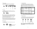
Line Rate
These switches control the signalling rate on the line (RJ-48S port).
They should match the speed of your digital service.
SW1-1 SW1-2 SW1-3 Setting
On On On 2.4 kbps
On On Off 4.8 kbps
On Off On 9.6 kbps
On Off Off 19.2 kbps
Off On On 56 kbps
Off On Off 64 kbps
Off Off Off Force configuration pointer to
default to hardware switches
(See Section 4.2)
(continued)
For line rates of 56 and 64 kbps, it is possible to operate the DTE
interface at a lower rate. To do this, set these switches to 56 or 64 kbps
and set the Rate Converter/DTE Rate switches as required.
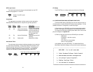
Circuit Assurance
On dedicated circuits, the transmitter and the CTS output can be
configured to go On only when a working communication circuit is
established. If Circuit Assurance is used, enable it on only one end of
the communication link. In Switched 56 mode, this switch should be set
to On on both ends of the circuit.
Circuit
SW1-4 Assurance Description
On Enabled CTS will go low and the
transmitter will be held off if the
receiver is in the No Signal state
or CD is low
Off Disabled The transmitter and CTS will
operate without regard to the
receiver state
RTS
The RTS input can be forced on, ignoring the terminal’s RTS
signal. RTS controls the transmitter by either sending the user’s data or
sending an idle code. Force RTS should be enabled in Switched 56
mode.
SW1-5 RTS Description
Off Forced On An On (high) condition is trans-
mitted regardless of the state of
this unit’s RTS input
On Follows DTE The RTS input controls the
transmitter
Note: At 64K line rate, RTS is always Forced On.
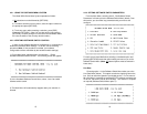
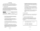
9 10
ON
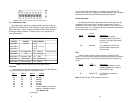
Figure 2. Close up of DIP switches showing ON/OFF positions.
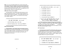
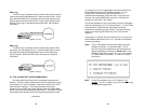
SWITCH SET 1 SUMMARY TABLE
56,000 bps
}
Figure 3. Summary of switch settings, showing factory defaults
Position Function Factory Default
Switch SW1-1 Line Rate Off
Switch SW1-2 On
Switch SW1-3 On
Switch SW1-4 Circuit Assurance Off Disabled
Model 2510 Enabled
Switch SW1-5 RTS Off Forced On
Switch SW1-6 Character Length Off 10 Bit
Switch SW1-7 Data Format Off Synchronous
Switch SW1-8 DSR Loop Status Off DSR Off