


3.0 INSTALLATION
This section describes connection of the Model 2500 Series to the
DTE and telco (line) interfaces, as well as AC power connection
3.1 DTE INTERFACE CONNECTION
The Model 2500 Series has connectors for both V.35 and RS-232
interfaces. Signals output by the Model 2500 Series will appear on
both interfaces. An internal jumper is used to select which interface will
be used for input. With the jumper in the factory default position, the
Model 2500 Series automatically selects which interface will be used for
input. If the DTR signal on the RS-232 is active, then the RS-232
inputs are selected. Otherwise, the V.35 inputs are selected. If you
choose, you may re-configure the Model 2500 Series for fixed V.35 or
fixed RS-232 operation. To do this, follow the steps below:
1) Turn the power switch off.
2) Remove the power cord from the unit.
3) Remove the two screws on the rear panel and slide the board
out from the rear.
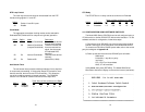
4) Locate the DTE port selection jumper near the middle of the PC
board. This jumper has three pins, two of which are covered by
the strap. The factory position of the jumper is with the strap
covering the two pins closest to the rear of the unit.
5) To reconfigure the Model 2500 Series for fixed V.35 operation,
move the strap so that it covers the two pins closest to the front
of the unit.
6) To reconfigure the Model 2500 Series for fixed RS-232
operation, remove the strap altogether (be sure not to lose the
strap).
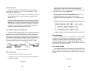
3.1.1 V.35 INTERFACE PORT
For V.35 operation, attach your DTE (terminal) cable to the 34 pin
rectangular M/34 connector. The DTE cable should be pinned
according to the diagram in Appendix D.
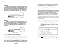
3.1.2 RS-232 INTERFACE PORT
For RS-232 operation, attach your DTE (terminal) cable to the 25
pin DB-25 connector. The DTE cable should be pinned according to
the diagram in Appendix D.
6
2.3 SUPPORTED APPLICATIONS
The Model 2500 Series includes three units: the Model 2500 All-
Rate CSU/DSU, the Model 2510 Switched 56 CSU/DSU and the Model
2520 All-Rate/Switched 56 CSU/DSU. Depending upon the unit
selected, the Mode 2500 Series supports three distinct modes of
operation. These are outlined in the descriptions and table below:
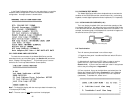
Dedicated DDS/Clear Channel Operation (Models 2500, 2520)
The unit can be easily configured for dedicated DDS/Clear Channel
operation by means of the dip switches on the bottom of the enclosure,
or by means of the software control port. Set the Line Rate to match
the rate of service to which you subscribe. Set the Mode switches for
Network Clocking. The Rate Converter and the Data Format options
should be set as required for your application. The remaining options
may need to be set depending on your terminal equipment and your
application.
Switched-56 Operation (Models 2510, 2520)
The unit can be used in Switched 56 applications. Set the Line
Rate to 56 kbps. Set the Mode switches for Switched 56, and enable
Force RTS and Circuit Assurance. Dial or store a number using the
control port. The Rate Converter and the Data Format options should
be set as required for your application. The remaining options may
need to be set depending on your terminal equipment and your
application.
Campus Area Short Haul Operation (Models 2500, 2520)
The unit can also be used for campus area point-to-point short-haul
applications on private twisted-pair wires. Set the Line Rates the same
on both units. Set the Mode switch for the appropriate Transmit Clock
Mode for your application. Internal, External and Looped Clock Modes
are available. Set the remaining options as needed by your terminal
equipment or your application.
5
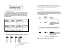
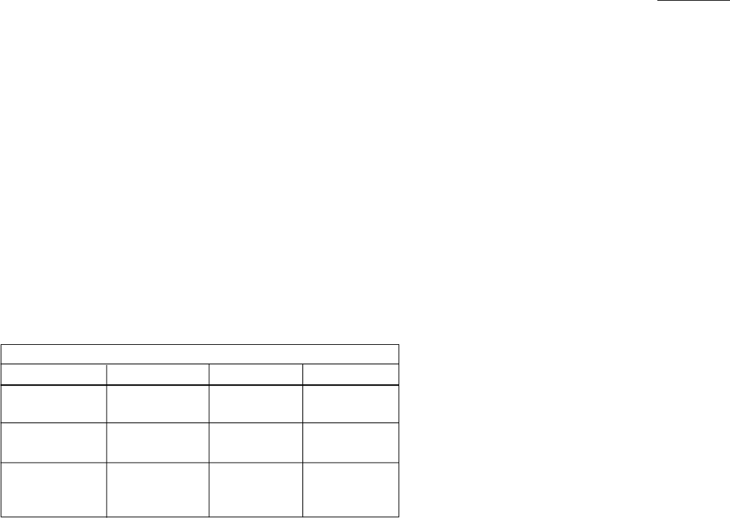
MODEL 2500 SERIES APPLICATIONS
2500 2510 2520
Line Rate Switches All line rates 56 Kbps only All line rates
Supported Supported
Mode Switches Supports all modes Switched 56 only All modes
except Sw-56 Supported
Not Supported Supported Supported
Dialing
Comments