


4.0 CONFIGURATION
Before you can operate your Model 2500 Series CSU/DSU, you
must configure the unit. Configuration may be done using the
externally accessible hardware switches or by using the software
switches. Software switches can be accessed from the front panel
control port using a VT-100 type RS-232 terminal that responds to ANSI
escape sequences.
4.1 CONFIGURATION USING HARDWARE SWITCHES
The Model 2500 Series defaults to the use of hardware switches for
configuration. The unit can also use software switches for configuration
(see Section 4.3), in which case the hardware switches will be ignored.
Note: If you are attempting to configure the unit using hardware
switches and find they are being ignored, you will need to override
the software switches and force the unit back into hardware switch
mode. To do this, power-up the unit once with the Line Rate (SW1-
1, 1-2, 1-3) set to Off, Off, Off. Then set the hardware switches as
you require and power-up the unit again.
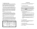
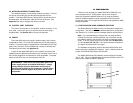
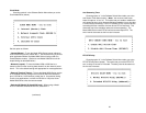
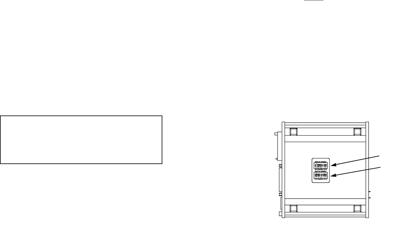
The hardware configuration mode for the Model 2500 Series uses
sixteen externally accessible DIP switches. Figure 1 (below) shows the
location of the Model 2500 Series' DIP switches.
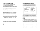
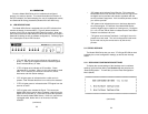
The Model 2500 Series’ DIP switches can be configured as either
“On” or “Off”. Figure 2 (opposite page) shows the orientation of the DIP
switches with respect to ON/OFF positions.
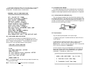
3.2 NETWORK INTERFACE CONNECTION
The Network Interface is an 8 position modular connector. Connect
this port to the RJ-48S jack provided by the digital data service
provider. If the Model 2500 Series is being used for private short haul
communication, the twisted pair cable will connect to this port. See
Appendix D for the pin assignments of this connector.
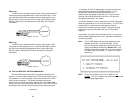
3.3 CONTROL PORT INTERFACE
The Control Port Interface is an 8 position modular connector. If it is
to be used, connect this port to an asynchronous terminal using a
shielded cable. See Section 4.4 for control port operation.
3.4 POWER
The model 2500 series has a built-in powers supply that is factory
configured for either 115 or 230 VAC, depending on how the product is
ordered. This power supply is equipped with a shrouded male IEC-320
power entry connector, and is available with a variety of domestic and
international power cords (see Appendix C).
In order for the Model 2500 Series unit to operate, the power cord
(supplied) must be attached to the power entry connector on the rear of
the unit and plugged into an outlet that is easily accessible. The power
switch on the rear of the unit must also be turned ON.
87
WARNING! There are no user-serviceable parts in the
power supply section of the Model 2500 Series. Voltage
setting changes and fuse replacement should only be
performed by qualified service personnel. Contact Patton
Electronics Technical support at (301)975-1007 for more
information.
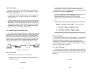
Figure 1. Model 2500 Series bottom view, showing location of DIP switches
SW2
SW1