


5.0 OPERATION
Once the Model 2500 Series unit is installed and configured
properly it is ready to operate. This section describes the function of
the LED indicators, the status displays, the use of loopback test modes,
and Switched 56 dialing procedures (Models 2510 and 2520 only).
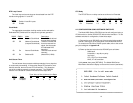
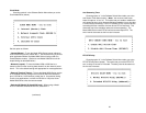
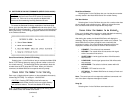
5.1 LED DESCRIPTIONS
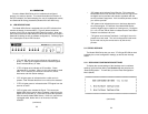
The Model 2500 Series is equipped with nine LED indicators that
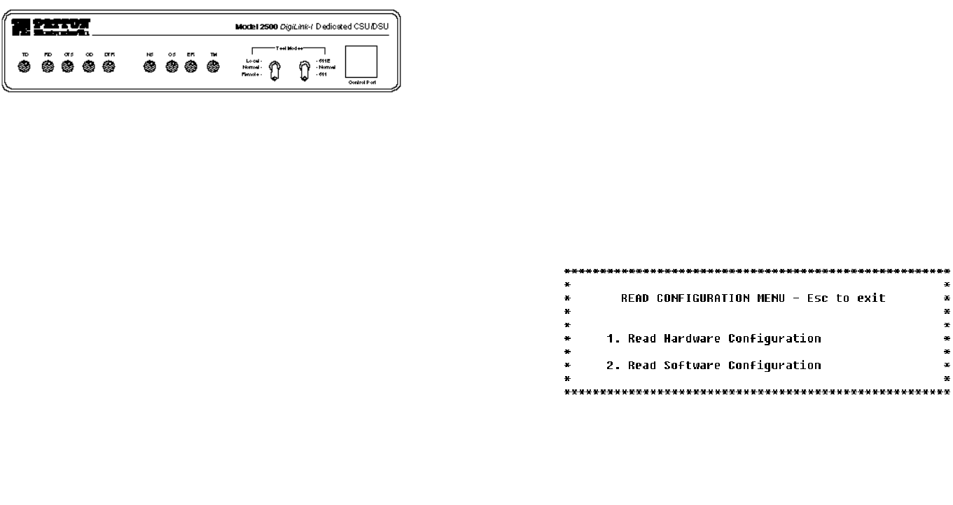
monitor the status of communication. Figure 5 (below) shows the
location of the LEDs on the Model 2500 Series front panel. Note also
the location of the test mode switches and RS-232 control port (used in
Switched 56 dialing as well as software configuration). Following Figure
5 is a description of each LED’s function.
• “TD” and “RD” will glow red to indicate an Idle condition or
Binary “1” data on the respective terminal interface signals.
Green indicates Binary “0” data.
• “CTS” will glow red to indicate an Off condition. Green
indicates an On condition. When on, the unit is ready to send
data. If CTS remains off, check the Forced RTS, Circuit
Assurance and Anti-Stream settings.
• “CD” will glow green to indicate that the a valid carrier is
present. Red indicates that there is no valid carrier detected.
• “DTR” will glow green to indicate that the DTR signal from the
terminal is active.
• “NS” will glow red to indicate No Signal. This means the
Model 2500 Series receiver does not detect a signal from the
digital service provider (or, in the case of short-haul operation,
from the remote Model 2500 Series). If NS is lit, check for an
unplugged cable, broken wire or an incorrect Line Rate
selection.
(continued)
• “OS” glows red to indicate Out-of-Service. This means the
Model 2500 Series has received an Out-of-Service signal from
the digital service provider and indicates a problem with the
service provider’s equipment. If this condition persists, contact
your service provider.
• “ER” glows red to indicate that an error has been detected in
the received signal. ER will flash if the Model 2500 Series
receives illegal bi-polar violations or framing errors. During the
511 or 511/E test, ER will flash to indicate that the Test Pattern
Detector has detected a bit error.
• “TM” glows red to indicate Test Mode. It will light if the unit is
placed into a test mode. The unit can be placed in test mode
by the local user, by the remote user or by the service
provider.
5.2 STATUS DISPLAYS
The Model 2500 Series lets you use a VT-100 type RS-232 terminal
to display the current configuration settings, as well as the line/loop
status.
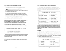
5.2.1 DISPLAYING CONFIGURATION SETTINGS
To display the current settings of the hardware and /or software
switches, go to the Main Menu (see Section 4.2) and select item 2,
“Read Configuration”. This will take you to the Read Configuration
Menu (below).
(continued)
23
24
Figure 5. The Model 2500 Series' front panel LEDs