


7
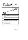
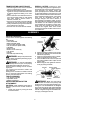
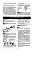
30 inches
(76 cm)
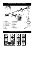
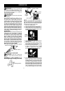
CONFIGURING YOUR UNIT
Youcan configure your unit using acuttinghead
for grass and light weeds, or a weed blade for
cutting grass, weeds, and brush up to 1 cm in
diameter. To assemble your unit, go to the sec-
tion for the desired configuration and follow the
instructions.
ASSEMBLY INFORMATION --
TRIMMER HEAD
TRIMMER
HEAD
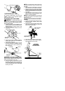
NOTE:Remove theblade andmetal shieldbe-
fore attaching the plastic shield and trimmer
head. To re mo ve bl ade, align hole in the dust
cup with theholein theside ofthe gearboxby
rotating the blade. Insert a smallscrewdriver
intoalignedholes. Thiswillkee pth esha ftfrom
turning while loosening the b lade nut. Remove
blade nut by turning clockwise. Remove the
screwdriver . Remove both washers and blade.
Toremove metal shield, loosen and removethe
four mounting screws. See ATT ACHING THE
MET AL SHIELD and INST ALLA TION OF THE
MET ALBLADE forillustrations. Besure tostore
all parts and instructions for future use.
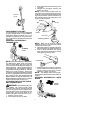
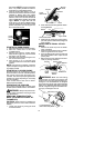
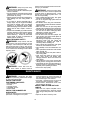
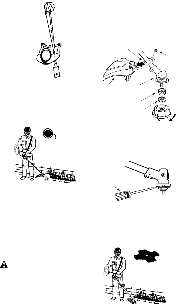
ATTACHING THE PLASTIC SHIELD
ANDTRIMMERHEAD
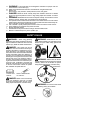
WARNING: Theshield must beprop-
erly installed. The shield provides partial
protection tothe operatorandothers fromthe
risk of thrown objects, and isequipped witha
line limiterblade whichcuts excess linetothe
proper length. The line limiter blade (on un-
derside of shield) is sharp and can cut you.
1. Remove nut from shield.
2. Insert bracket into slot on shield.
3. Pivot shielduntil boltpasses throughhole
in bracket.
4. Reinstall nut and tighten securely with
wrench (provided).
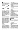
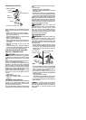
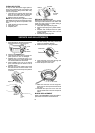
NOTE: If your unit has a plastic cover over
thethreads onthethreadedshaft,removethe
coveringto exposethethreads.Beforeinstal-
lingthetrimmerhead,make surethedustcup
and retaining washer are positioned on the
gearbox as shown below.
Nut
Retaining Washer
Dust Cup
Bracket
Slot
Shield
Gearbox
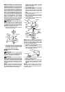
NOTE: Make sure all parts are properly
installed as shown in t he illustration before
installing the trimmer head.
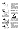
5. Align holein thedust cupwith thehole inthe
side of thegearbox by rotating the dust cup.
6. Insert a small screwdriver into aligned
holes. Thiswillkeeptheshaft fromturning
while tigh tening trimmer head.
Screwdriver
7. While holding the screwdriver in position,
thread trimm er head onto the shaft i nthe
direction shown on the decal (counter-
clockwise). Tighten until secure.
NOTE: The retaining washer must be posi-
tioned with the raised section facing toward the
gearbox.
ASSEMBLY INFORMATION -- WEED
BLADE
WEED
BLADE