


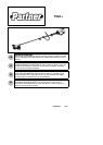

5
TRANSPORTING AND STORAGE
S Allow theengine tocool; secure unitbefore
storing or transporting in vehicle.
S Empty fuel tank beforestoring or transport-
ingtheunit.Useupfuelleftinthecarburetor
by starting engine and letting it run until it
stops.
S Store unitandfuel inan areawhere f uelva-
pors cannot reach sparks or open flames
from water heaters, electric motors or
switches, fu rnaces, etc.
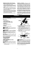
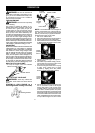
S Storeunitso linelimiter cannotaccidentally
cause injury. Unitcan behung bytheshaft.
S Always install transport guard on bladebe-
fore transporting or strorage.
S Store the unit out of the reach of children.
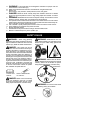
SPECIAL NOTICE: Exposure to vibra-
tions through prolongeduseof gasoline pow-
ered hand tools could cause blood vessel or
nerve damage in the fingers, hands, and
joints of people prone to circulation disorders
or abnormal swellings. Prolonged use incold
weatherhas beenlinkedtobloodvesseldam-
age inotherwise healthypeople. Ifsymptoms
occur such as numbness, pain, loss of
strength, change in skin color or texture, or
loss of feeling in the fingers, hands, or joints,
discontinuetheuseofthistooland seekmed-
ical attention. An anti-vibration system does
not guarantee the avoidance of these prob-
lems. Users who operate power tools on a
continual and regular basis mus t m onitor
closely theirphysicalconditionand thecondi-
tion of this tool.
ASSEMBLY
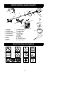
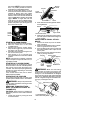
CARTON CONTENTS
Check carton contents against the following
list:
S Powerhead
S Lower attachment
S Blade and blade shield
S Trimmer head and plastic shield
S Nut(screwedontoplasticshield)
S Handlebar
S Bra ck et cove r
S Bra ck et cove r screws (2)
S Hex wrench
S Wrench
S Shoulder strap with warning
WARNING: Always stopunit anddis-
connectspark plugbefore performinganyas-
sembly procedures.
WARNING: If received assembled,
repeatallsteps toensure yourunit isproperly
assembled and all fasteners are secure.
Examine parts for damage. Do not use dam-
aged parts.
It is normal for the fuel filt er to rattle in the
empty fuel tank.
Finding fuelor oilresidue onmuffleris normal
due to carburetor adjustments and testing
done by the manufacturer.
TOOLS REQUIRED
S Hex wrench (provided)
S Adjustable wrench
S Phillips screwdriver
INSTALLING BRUSHCUTTER
ATTACHMENT
CAUTION:
When installing brushcutter at-
tachment, place the unit on a flat surface for
stability.
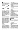
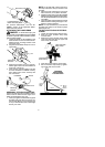
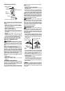
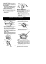
1. Loosen the coupler by turning the knob
counterclockwise.
Coupler
Knob
LOOSEN
TIGHTEN
Shipping
protector
2. Remove shipping protector from coupler .
3. Remove the shaft cap from the b rushcutter
attachment (if present).
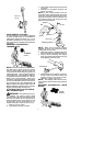
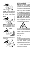
4. Position locking/release button of a ttach-
ment into guide recess of coupler.
5. Push theattachment intothe coupleruntil
the locking/release button snaps into the
primary hole.
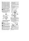
6. Before using the unit, tighten the knob se-
curely by turni ng clo ckwise.
Coupler Primary Hole
Upper
Shaft
Locking/
Release
Button
Lower
Attachment
Guide Recess
WARNING: M ake sure the locking/
release button is locked in the primary hole
and theknob is securely tightened beforeop-
erating the unit. Al l attachm en ts are designed
to be used in the primary hole unless o therwise
stated in the applicable attachment instruction
manual. Using thewronghole couldlead toseri-
ous inj ury or d amag e t o t he u nit.