


10
than6pulls.
NOTE: Ifenginestilldoesn’t
start, it is probably flooded. Proceed to
STARTING A FLOODED ENGINE.
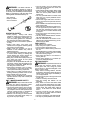
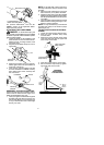
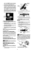
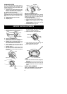
9. Once the engine starts, allow it to run 10
seconds,then movethechokelever toOFF
CHOKE by aligning lever with position
shown on decal (see following illustration).
Allow the unit to run for 30 more seconds at
OFF CHOKE before releasing the throttle
trigger.
NOTE: If engine dies with the
choke lever in the OFF CHOKE p osition,
move the choke lever to the HALF CHOKE
position and pull the rope until engine runs,
but no more th an 6 pulls.
Choke
position
decal
STARTING A WARM ENGINE
1. Move ON/OFF switch to the ON position.
2. Move the choke lever to the HALF
CHOKE position.
3. Squeeze and hold the throttle trigger .
Keep throttle trigger fully squeezed until
the engine runs smoothly.
4. Pullstarterropesharply untilengineruns,
but no more than 5 pulls.
5. Allow engine to run 15 seconds, then
movethe chokelever totheOFFCHOKE
position.
NOTE: If engine has not started, pullstarter
rope5morepulls.Ifenginestill d oesnotrun,it
is probably flooded.
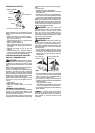
STARTING A FLOODED ENGINE
Flooded engines can be started by placing
the choke lever in the OFF CHOKE position;
then, pull the rope to clear the engine of ex-
cessfuel.Thiscouldrequirepullingthestarter
handle ma ny times depending on how badly
the unit is flooded.
If the unit still doesn’t start, refer to TROU-
BLESHOOTING TABLE.
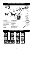
OPERATING THE COUPLER
This mode l is equipped with a coupler which
enables optional attachments to beinstalled.
WARNING: Always stopunit anddis-
connect spark plugbeforeremoving orinstal-
ling attachments.
REMOVING TRIMMER ATTACH-
MENT (OR OTHER OPT IONAL AT-
TACHMENTS)
CAUTION:
When removing or installing at-
tachments, placethe uniton a flat surface for
stability.
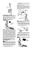
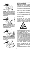
1. Loosen the coupler by turning the knob
counterclockwise.
Coupler
Knob
LOOSEN
TIGHTEN
Upper
Shaft
Lower
Attachment
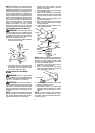
2. Press and hold the locking/release button.
L
ocking
/
Release
Button
Coupler
Upper Shaft
Lower Attachment
3. Whilesecurelyholdingtheengineandup-
per shaft, pull the attachment straight out
of the coupler.
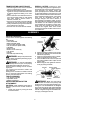
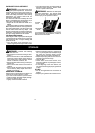
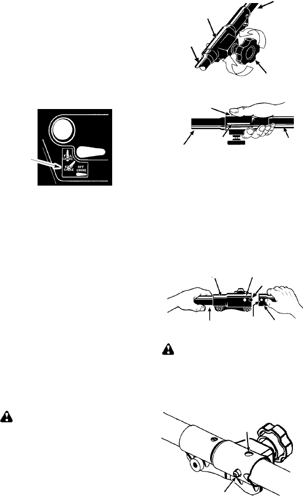
INSTALLING OPTIONAL ATTACH -
MENTS
1. Remove the shaft cap f rom the attach-
ment (if present).
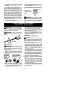
2. Position locking/release button of a ttach-
ment into guide recess of coupler.
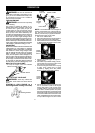
3. Push theattachment intothe coupleruntil
the locking/release button snaps into the
primary hole.
4. Beforeusing theunit, tightenthe knobse-
curely by turning clockwise.
Coupler
Primary Hole
Upper
Shaft
Locking/
Release
B
u
t
t
o
n
Attachment
Guide Recess
WARNING: M ake sure the locking/
release button is locked in the primary hole
and theknob is securely tightened beforeop-
erating the unit. Al l attachm en ts are designed
to be used in the primary hole unless o therwise
stated in the applicable attachment instruction
manual. Using thewronghole couldlead toseri-
ous inj ury or d amag e t o t he u nit.
Locking/Release
Button in Primary Hole
Secondary Hole