


© National Instruments Corporation 29 NI PXI-5422 Calibration Procedure
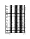
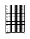
13. Measure the negative DC voltage out of the NI PXI-5422. Record
negative DC voltage out measurement in the Measured Negative Offset
column of Table 5.
14. Subtract the Ideal Negative Offset from the Measured Negative Offset
and record the result under Error Negative Offset. The Error Negative
Offset should be less than or equal to the limit you are using.
15. Call
niFgen_AbortGeneration (niFgen Abort Generation VI) to
abort the waveform generation using the following parameter:
• vi: The session handle returned from
niFgen_init
16. Return to step 5 until all iterations are completed.
17. Verify that all errors are less than or equal to the limit you are using.
If any of the errors are greater than the Calibration Test Limit or the
Published Specification, perform an external adjustment.
Verifying the Gain of the Direct Path
To verify the gain of the NI PXI-5422 Direct path, complete the following
steps:
Note The offset is not adjustable for the Direct path.
1. Call
niFgen_SetAttributeViReal64 to set the offset (niFgen
property node: Arbitrary Waveform Output»Arbitrary
Waveform Offset) using the following parameters:
• vi: The session handle returned from
niFgen_init
• channelName: "0"
• attributeID: NIFGEN_ATTR_ARB_OFFSET
• value: 0
2. Call niFgen_SetAttributeViInt32 to set the analog path (niFgen
property node: Output Attributes»Analog Path) using the following
parameters:
• vi: The session handle returned from
niFgen_init
• channelName: "0"
• attributeID: NIFGEN_ATTR_ANALOG_PATH
• value: NIFGEN_VAL_DIRECT_ANALOG_PATH
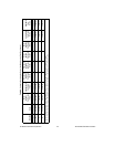
3. Repeat steps 4 through 15 for each of the seven iterations listed
in Table 6, changing the Gain value for each iteration. You can use
Table 6 to record the results of these steps.