


PAGE50 — SP7060 PAVEMENT SAW • OPERATION MANUAL — REV. #0 (02/13/09)
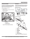
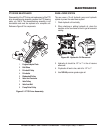
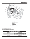
CIRCUIT BREAKERS AND STARTER RELAYS
Thermal circuit breakers and glow plug starter relays are located
behind the console access cover at the top of the console.
See Figure 59.
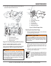
Under normal circumstances the circuit breakers do not require
service. They automatically reset when an overload condition
is corrected. If a breaker is cycling on and off, locate the cause
of the electrical overload and repair as required.
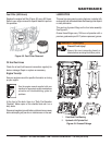
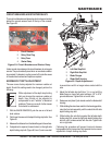
MAXIMUM CUT DEPTH ADJUSTMENT
The saw comes factory-adjusted for maximum usable cut
depth. Should this setting need to be changed, perform the
following:
1. With the BLADE REMOVED, park the saw on a flat and
level surface.
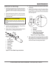
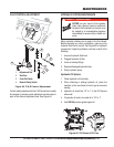
2. Fully lower the saw onto the depth limiting stop bolts. See
Figure 60.
3. Measure the distance from the blade flanges to the surface.
4. If adjustment is required, loosen locknut on the right-side
depth limiting stop bolt (Figure 60, item 2) and screw bolt
MAINTENANCE
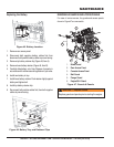
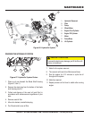
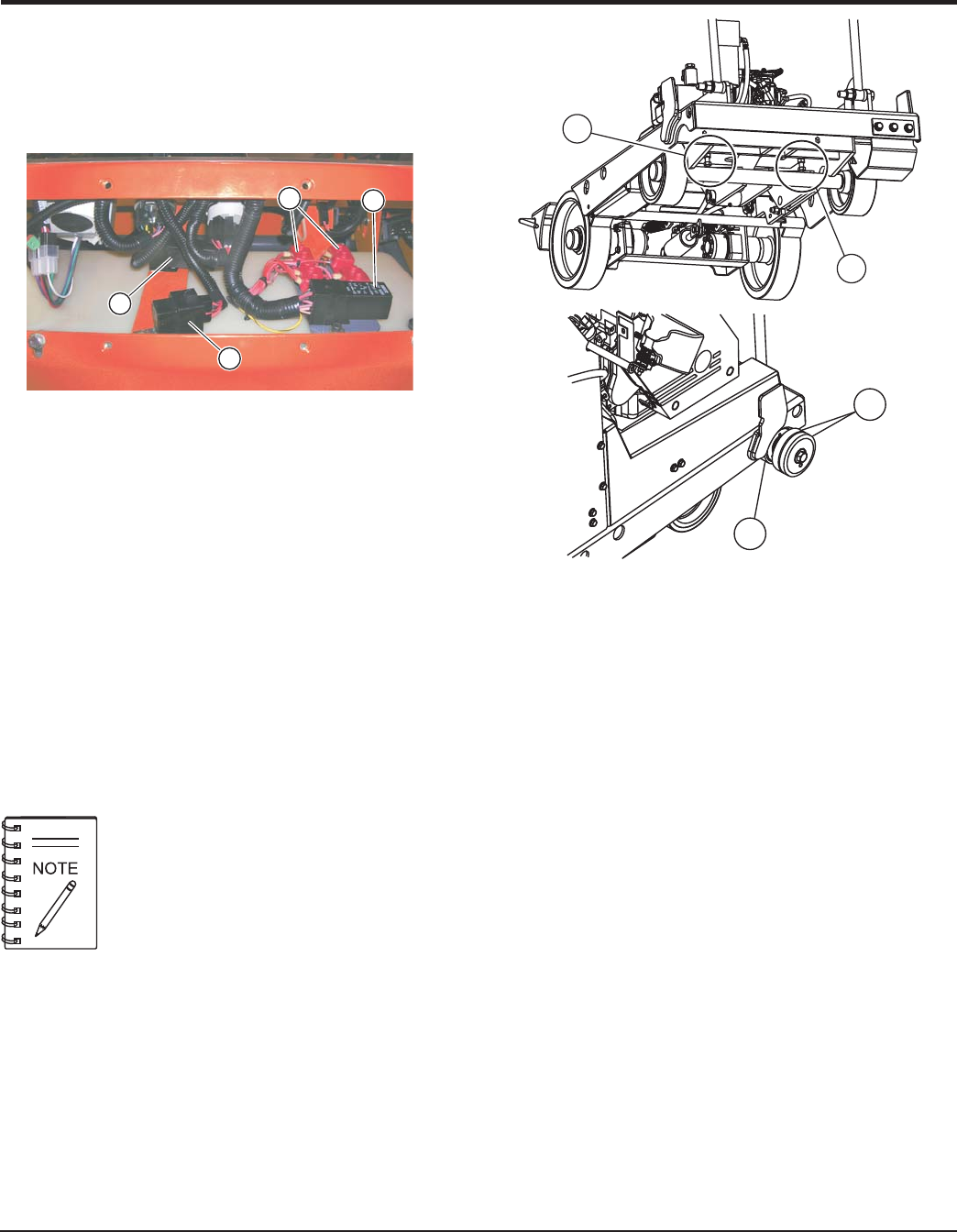
Figure 59. Circuit Breakers and Starter Relay
1
2
3
4
1. Circuit Breakers
2. Relay, Glow Plug
3. Delay Timer
4. Starter Relay
While adjustment of the depth stop limiting
bolts can change the maximum usable cut
depth, they should not be adjusted to
compensate for unit “wobble” or blade/cut
problems. These are a result of other issues
that should be addressed.
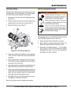
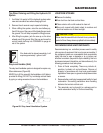
Figure 60. Depth Adjustment
1. Left-Side Stop Bolt
2. Right-Side Stop Bolt
3. Blade Flanges
4. Blade Shaft Housing
3
4
1
2
in several turns until it no longer makes contact with the
axle.
5. Adjust the left-side stop bolt (item 1) in or out until the
blade flange or lower belt guard achieves 1/8" to 3/16"
ground clearance. Tighten lock nut on left side.
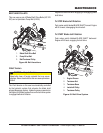
6. Raise saw and place 2 jack stands under the blade shaft
housing.
7. While holding the raise-lower switch in the lowering position,
raise the front axle assembly until it contacts the left-side
depth limiting stop bolt.
8. While holding the axle firmly against the left-side depth
limiting stop bolt, screw the right-side depth limiting stop
bolt out until it makes contact with the axle. Tighten lock
nut on right side.
Following this procedure will prevent torsional stresses
being applied to the frame when fully lowered due to uneven
adjustment of depth limiting stop bolts.