


PAGE48 — SP7060 PAVEMENT SAW • OPERATION MANUAL — REV. #0 (02/13/09)
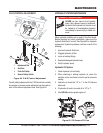
3. Lock down the transaxle attachment bolts when the
appropriate alignment distance is set.
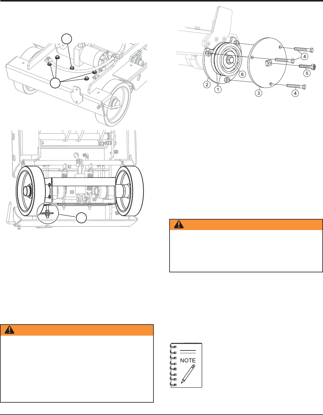
BLADE FLANGE REMOVAL/INSTALLATION
Correct removal or installation of the inner blade flange requires
a flange puller (p/n 18503). See Figure 56, items 2 and 3.
MAINTENANCE
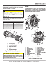
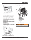
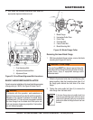
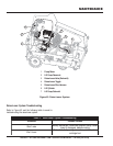
Figure 55. Drive Wheel Alignment Bolt Locations
1. Pivot Attachment Bolt
2. Adjustment Attachment Bolts
3. Adjustment Screw
3
1
2
WARNING
If unfamilar with this operation, seek assistance or
training from someone that is familar with this operation.
Because of the tapered fit between the blade flange
and blade shaft, 5-10 tons of force is required to release
the inner flange from the blade shaft. Both parts and
tools can become dangerous projectiles if instructions
are not followed properly.
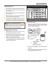
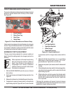
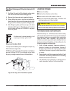
Removing the Inner Blade Flange
1. With the outer blade flange in place, remove the blade
mounting bolt (Figure 56, item 6).
2. While the 3 perimeter bolts (item 4) hold the two puller
plates together, slide the horseshoe plate (item 2) of
the flange puller behind the shaft side of the inner
flange.
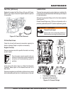
3. Tighten the center puller bolt (item 5) to remove the
inner flange from the blade shaft.
WARNING — Outer Flange
The outer flange MUST be in place to prevent the puller
assembly and inner flange from flying off when the taper
breaks loose. Injury or equipment damage could
otherwise result.
If the inner flange does not readily break free
from the tapered blade shaft while the center
puller bolt is tightened, lightly tap on the center
puller bolt to allow the flange to break free from
the shaft.
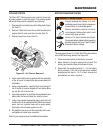
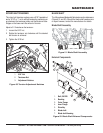
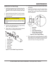
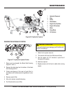
Figure 56. Blade Flange Puller
1. Blade Flange
2. Horseshoe Puller Plate
3. Puller Plate
4. Perimeter Bolt
5. Center Puller Bolt
6. Blade Mounting Bolt