


SP7060 PAVEMENT SAW • OPERATION MANUAL — REV. #0 (02/13/09) — PAGE 47
MAINTENANCE
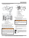
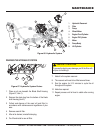
Removal and Replacement
To ensure correct blade shaft/wheel alignment, this
operation should be performed by an authorized service
center.
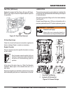
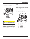
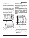
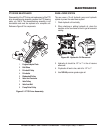
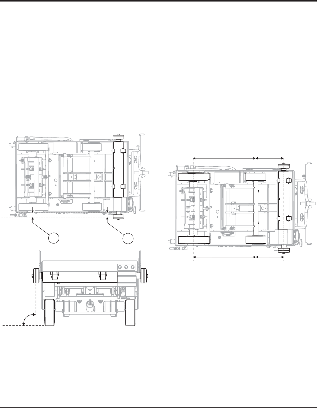
Blade Alignment
Maintaining proper blade and drive system alignment will
allow the saw to cut lines that are straight without much
effort. Therefore the blade shaft flanges MUST be
equadistant to the sides of the saw, (+/- .030"). See Figure
53 below where distance A must equal distance B.
The second requirement for the blade is that it MUST be square
to horizontal (90
o
to flat surface). See Figure 53.
Figure 53. Blade Alignment Requirements
90
o
A
B
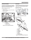
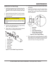
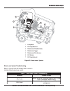
DRIVE SYSTEM ALIGNMENT
In addition to blade alignment, maintaining proper blade
and drive system alignment will allow the saw to cut lines
that are straight without much effort. Therefore the front
wheels and blade shaft axles MUST be at right angles to
the frame edge.
In Figure 54, you see the distance “A” on the right side is
shown as “A + .187"” which means that the distance
between centers of the front and rear drive axles are 3/16"
longer than on the opposite side. This will have the effect
of causing the saw to “steer” slightly to the left. After
becoming familar with the saws particular sawing
characteristics, the operator may wish to have this alignment
altered to fit his own preferences or to fit a particular
application.
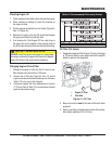
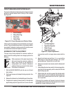
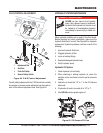
Drive System Alignment Adjustment
The drive wheels are aligned by adjusting the entire rear
drive assembly.
1. Loosen the transaxle attachment bolts just enough to
move the transaxle. Do not completely loosen the bolts.
2. Loosen and tighten the alignment jackscrew nuts to
move the transaxle, and thus the wheels, in the
appropriate direction to achieve the desired alignment
distance (Figure 54).
A
A + .187”
X
X
Figure 54. Wheel Alignment Requirements