


PAGE 54 — DCA-60SSI2 — PARTS AND OPERATION MANUAL — REV. #3 (09/15/01)
DCA-60SSIU — MAINTENANCE
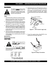
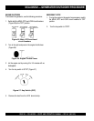
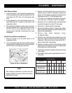
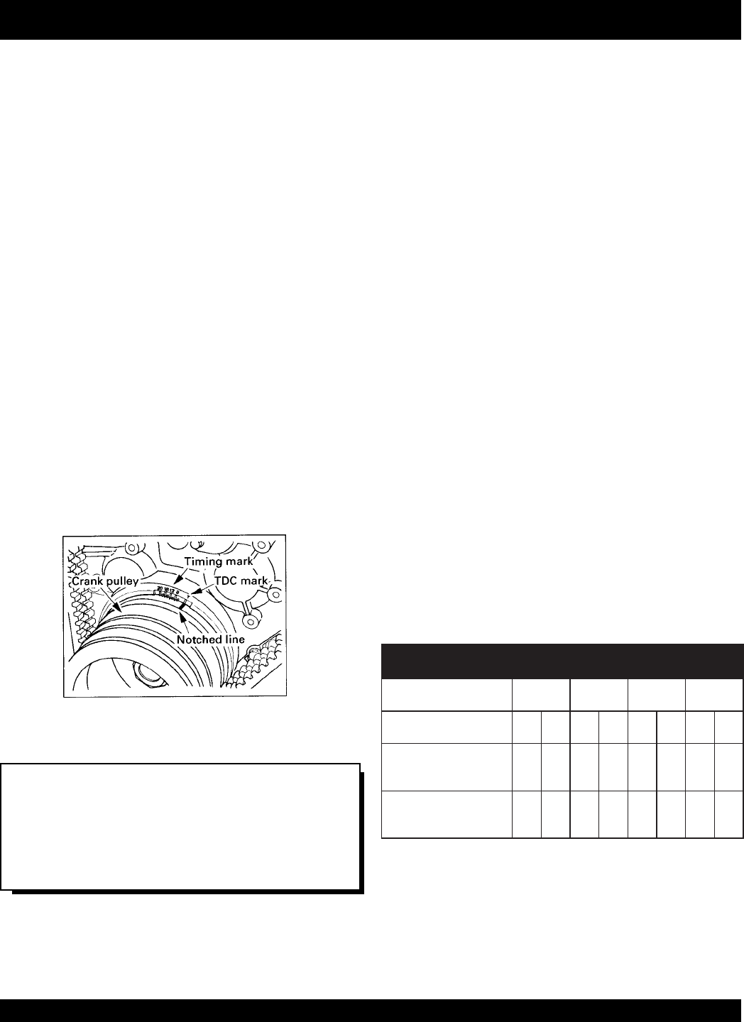
Figure 58. Valve Adjustment
Valve Clearance Check
1. In order to bring No. 1 or No. 4 cylinder to top dead center
in the compression stroke, align the notched line on the
crank pulley with TDC mark on the timing gear case
cover.
2. Do the adjustment on the circle marked valves in the
below table where No. 1 cylinder is at the center in the
compression stroke.
3. After adjustment started from either piston top center,
turn the crankshaft 360
o
to align the notched line with
the TDC mark to do the adjustment again on the
remaining valve. See Table 16 and Figure 55 for valve
arrangement.
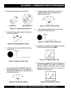
Injection Timing Check and Adjustment
1. Bring No. cylinder to the top dead center on the
compression stroke.
2. Turn the crankshaft pulley clockwise (viewed at engine
front) and align the notched line on the crank pulley with
the TDC mark on the timing gear case cover.
3. Remove the timing check hole cover at the front of
injection pump to check the alignment between the
pointer “a” on the injection pump gear lock plate and the
projected area mark “b” on the timing gear case.
4. If “a” and “b” are in alignment, the timing is set correctly.
If not, follow nos. 1-3 until the “a” and “b” are aligned.
5. Reversely turn the crankshaft pulley counterclockwise
viewed at the engine front about 30
o
crank angle.
6. Remove No. 1 injection pipe from the engine.
7. Remove the injection pump No. 1 delivery valve holder,
delivery valve and spring and reinstall the delivery valve
holder on the original place.
8. Delivery valve holder tightening torque:
39~44Nm(29~33lbft.)
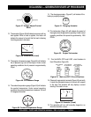
9. Slowly turn the crankshaft pulley clockwise and at the
same time continue to feed the fuel with pumping the
Feed pump. When the fuel stop to flow out from No. 1
delivery valve holder, stop pumping.
10. Observe and make sure which mark (injection starting
angle line) on the timing gear case cover is aligning with
the notched line on the crank pulley.
11. The timing line shows the injection starting crank angle
of the engine.
12. The injection starting crank angle should be at the 14
o
timing mark.
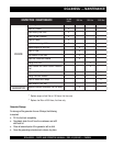
tnemtsudAevlaV.51elbaT
)tsuahxE=E;telnI=I(
.oNrednilyC1234
tnemegnarrAevlaV IEIEIEIE
pottasi1.oNnehW
ehtniretnecdaed
ekotsnoisserpmoc
XXX X
pottasi4.oNnehW
ehtniretnecdaed
ekortsnoisserpmoc
OO OO
NOTE:
Take necessary precautions to prevent dust and
foreign particles in the pump interior when timing
adjustments are made.