


DCA-60SSI2 — PARTS AND OPERATION MANUAL— REV. #3 (09/15/01) — PAGE 47
WARNING:
Before Starting
Engine
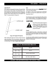
1. Check the lubricating oil level prior to starting the engine.
Make sure the generator is level. The oil level must be
maintained between two notches on the dipstick.
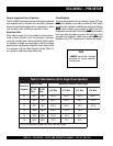
2. When there is not enough lubricating oil, fill the crankcase
with high grade motor oil. Use a high quality detergent
oil classified CC or higher (See Table 11 on page 43).
3. Check the coolant level in the radiator and subtank.
Replenish with antifreeze as necessary. Always maintain
the coolant level between the FULL and LOW markings
on the coolant container. Be sure that the radiator cap is
fastened securely.
4. Check the fuel level on the fuel gauge. If fuel is low, fill
the fuel tank with clean fresh unleaded automotive diesel.
If diesel spillage occurs, completely wipe up the spilled
fuel immediately.
Before Starting
Generator and Control Panel
CAUTION:
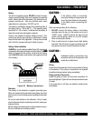
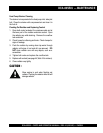
1. Be sure to disconnect the
electrical load and switch the
main, load main, load
main, load main, load
main, load
and
G.FG.F
G.FG.F
G.F
.C.C
.C.C
.C
.I..I.
.I..I.
.I.
circuit breakers (Figure 12) to the “OFF” position prior to
starting the engine.
NEVER start the engine with the
main,main,
main,main,
main,
GFCI GFCI
GFCI GFCI
GFCI
or
loadload
loadload
load
circuit breakers
in the ON position.
The engine's exhaust contains harmful
emissions.
ALAL
ALAL
AL
WW
WW
W
AA
AA
A
YS YS
YS YS
YS
ventilate the
exhaust when operating inside tunnels,
excavations or buildings. Direct exhaust
away from nearby personnel.
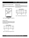
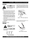
Figure 36. Main, GFCI and
Load Circuit Breakers
DCA-60SSI2 — GENERATOR START-UP PROCEDURE
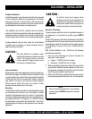
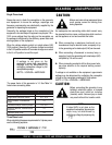
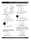
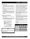
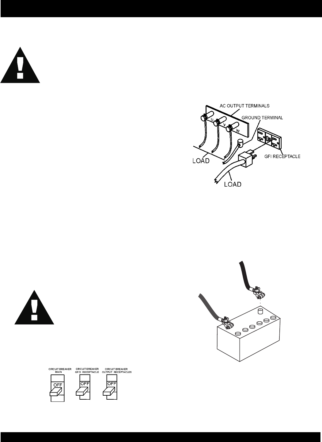
2. Connect the load to the UVW terminals as shown in
Figure 37. These terminals can be found on the output
terminal panel, (see page 22 Figure 6). To gain access
to the output terminals lift the UVW cover. Tighten
terminal nuts securely to prevent load wires from slipping
out.
Figure 37. UVW Terminal Lugs (Load)
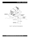
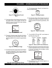
NEGATIVE
POSTIVE
BATTERY
3. Connect the negative battery cable (BLACK) to the
negative post on the battery (Figure 38).
Figure 38. Battery Connections