


DCA-60SSI2 — PARTS AND OPERATION MANUAL— REV. #3 (09/15/01) — PAGE 35
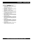
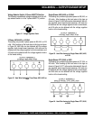
Receptacle Use
When the UVWO terminals are providing power, the recep-
tacle power availability will decrease.
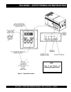
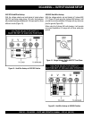
How To Read The Output Terminal Gauges.
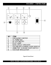
The gauges (Figure 15 and 17) and change-over switches
on the control panel DO NOT effect the generator output.
They are to help observe how much power is being supplied
at the UVWO legs.
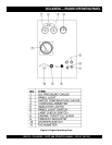
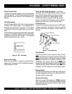
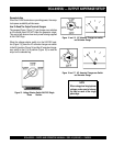
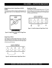
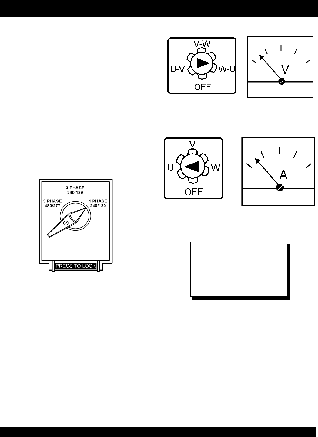
When the voltage selector switch is in the 240/120V posi-
tion (Figure 13), place the AC voltmeter change-over switch
to the W-U position (Figure 14) and the AC ammeter change-
over switch to the U or W position (Figure 16) to read the
output on the selected leg.
Figure 13. Voltage Selector Switch 240/120V Single
Phase Position
Figure 14 and 15. AC Voltmeter Change-over switch
and Voltmeter Gauge
Figure 16 and 17. AC Ammeter Change-over Switch
and Ammeter Gauge
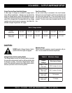
When using plural single phase
voltages, make sure to balance
the load on each of the single
phase legs.
NOTE
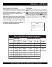
DCA-60SSIU — OUTPUT AMPERAGE SETUP