


PAGE 32 — DCA-60SSI2 — PARTS AND OPERATION MANUAL — REV. #3 (09/15/01)
DCA-60SSIU — OUTPUT TERMINAL PANEL
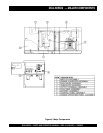
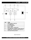
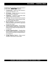
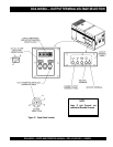
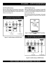
Output Terminal Panel
The output control panel is located on the rear (control panel)
end of the generator. The UNV lugs are protected by a face
plate cover that can be secured in the close position by a
pad lock.
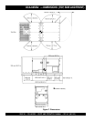
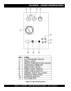
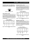
120 Volt Receptacle
One GFCI Duplex NEMA 5-20R (120V, 20 Amp) receptacle
is located on the output terminal. This receptacle can be
used anytime the generator is in operation. The receptacle
is controlled by the circuit breaker located on the control
panel.
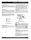
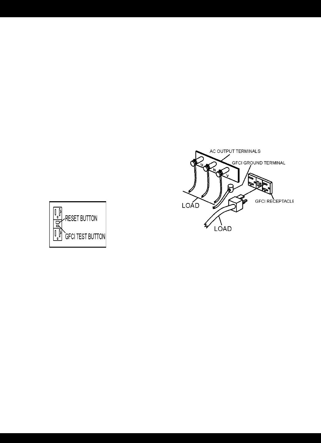
The reset button will reset the receptacle after being tripped.
Pressing the :Test Button” (Figure 8) in the center of this
receptacle will check the GFCI function. The receptacle
should be tested at least once a month.
Figure 10. GFCI Test Button
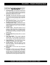
Connecting Load
Loads can be connected to the generator by the UVWO lugs or
the duplex receptacles. (See figure 3). Make sure to read the
operation manual before attempting to connect a load to the
generator.
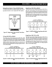
Maximum Output
The entire load connected to the UVWO lugs, all four slots in
the duplex receptacles, and the must not exceed 52.8 kW in
standby or 48 kW in prime output.
Generator Grounding
Make sure to ground the generator in EVERY application
prior to connecting a load. Generators are NOT grounded
just because they are mounted on trailers or other vehicles
that are on rubber tires.
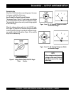
Twist Lock Dual Voltage Receptacles - To use these
receptacles, place the voltage selector switch in the single
phase 240/120 voltage position and adjust the output
voltage to 240 volts with the voltage regulator on the
Control Panel (Figure 8, page 28). Place the voltmeter
change-over switch to the U-W position and the ammeter
change-over switch to the U or W to read the output.
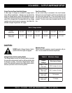
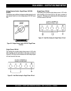
Circuit Breakers
To protect the generator from an overload,
a 3-pole, 150 amp,
main main
main main
main
circuit breaker is provided to protect the UVWO output
terminals from overload. In addition two single-pole, 20 amp
GFCIGFCI
GFCIGFCI
GFCI
circuit breakers are provided to protect the GFCI
receptacles from overload. Three 50 amp
loadload
loadload
load
circuit
breakers have also been provided to protect the load side of
the generator from overload. Make sure to switch
ALLALL
ALLALL
ALL
circuit
breakers to the "OFF" position prior to starting the engine.
Generator Grounding
Make sure the generator is properly grounded before
applying load. Generators are NOT considered grounded
when mounted on a trailer.
Figure 11. Load Application