


DCA-400SSK — PARTS AND OPERATION MANUAL (STD)— REV. #3 (09/17/01) — PAGE 49
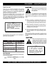
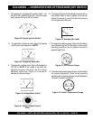
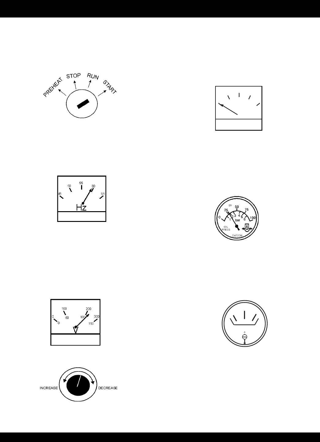
8. The generator's frequency meter (Figure 39) displays
the 60 cycle output frequency in HERTZ.
Figure 39. Frequency Meter (Hz)
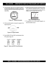
Figure 40. Voltage Meter (Volts)
9. The generator's voltage meter (Figure 40) displays the
120 VAC in VOLTS. If the voltage is not within the
specified frequency tolerance, use the voltage
adjustment control knob (Figure 41) to increase or
decrease the desired voltage.
A
0
40
60
75
20
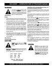
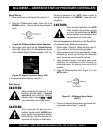
Figure 42. Ammeter (No Load)
Figure 41. Voltage Adjust Control
Knob
10. The ammeter (Figure 42) will indicate zero amps with no
load applied. When a load is applied, this meter will
indicate the amount of current that the load is drawing
from the generator’s alternator.
Figure 38. Engine Ignition Switch
7. If the generator is equipped with a ignition switch, turn
the key to “Start” position (Figure 38). Once the engine
starts, release the key to the “on” position.
DCA-400SSK — GENERATOR START-UP PROCEDURE (KEY SWITCH)
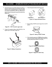
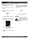
11. The engine oil pressure gauge (Figure 43) will indicate
the oil pressure (kg/ cm
2
)
of the engine. Under normal
operating conditions the oil pressure should be
approximately 25 psi.
Figure 43. Oil Pressure Gauge
12. The coolant temperature gauge (Figure 44) will indicate
the coolant temperature. Under normal operating
conditions the coolant temperature should be between
165 and 215 degrees Fahrenheit .
WATER
TEMP
Figure 44. Coolant Temperature Gauge