


PAGE 34 — DCA-400SSK — PARTS AND OPERATION MANUAL (STD)— REV. #3 (09/17/01)
DCA-400SSK — OUTPUT TERMINAL PANEL OVERVIEW
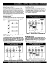
Circuit Breakers
To protect the generator from an overload, a 3-pole, 1000
amp,
main main
main main
main
circuit breaker is provided to protect the UVW
output terminals from overload. In addition two single-pole,
20 amp
GFCIGFCI
GFCIGFCI
GFCI
circuit breakers are provided to protect the
GFCI receptacles from overload. Three 50 amp
loadload
loadload
load
circuit
breakers have also been provided to protect the load side of
the generator from overload. Make sure to switch
ALLALL
ALLALL
ALL
circuit
breakers to the "OFF" position prior to starting the engine.
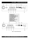
OUTPUT TERMINAL FAMILIARIZATION
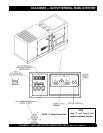
The “Output Terminal Panel” is provided with the following:
z
Two 120V GFCI receptacles, 20 amp
z
Three 120/240V output receptacles, 50 amp
z
Two 120V output receptacles, 20 amp (optional)
z
3 Circuit Breakers 240V @50 amps
z
2 GFCI Circuit Breakers 125V@ 20 amps
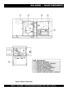
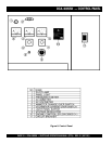
Control Box
The “Control Box” is provided with the following:
z
Main Circuit Breaker 1000 amps
z
Over-Current Relay
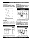
Output Terminal Panel
The Output Control Panel (See Figure 14) is located on the
right hand side (left from control panel) of the generator.
The UVWO lugs are protected by a face plate cover that
can be secured in the close position by a pad lock. (See
Figure 11).
120 Volt Recetacle
Two GFCI Duplex Nema 5-20R (120V, 20 Amp) recepacle is
provided on the output terminal. This receptacle can be
used anytime the generator is in operation. The receptacle
is controlled by the circuit breaker located on the control
panel.
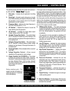
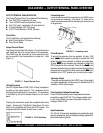
Pressing the reset button resets the receptacle after being
tripped. Pressing the "Test Button" (See Figure 12) in the
center of this receptacle will check the GFCI function. The
receptacle should be tested at least once a month.
FIGURE 12. GFCI Test Button
FIGURE 11. Output Terminal Cover
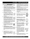
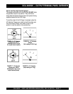
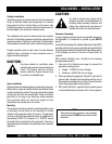
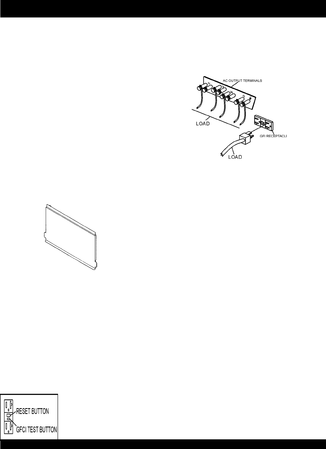
Connecting Load
Loads can be connected to the generator by the UVWO Lugs or
the convenience receptacles. (See figure 13). Make sure to
read the operation manual before attempting to connect a load
to the generator.
Maximum Output
The entire load connected to the UVWO Lugs, all four slots in
the duplex receptacles, and the must not exceed 352 kW in
standby or 320 in prime output.
Twist Lock Dual Voltage Receptacles
Three CS-6369 auxiliary power receptacles have been
provided to supply 208/120V. The voltage regulator knob
on the control panel may need to be used to adjust the
voltage to 208 or 416V.
Input Receptacles
Two 120 volt, 20 amp input receptacles are provided to supply
power to accessories, such as the battery charger (optional) or
jacket water heater (optional).
FIGURE 13. Connecting Load