


DCA-300SSK SERIES — PARTS AND OPERATION MANUAL (STD)— REV. #4 (03/27/06) — PAGE 23
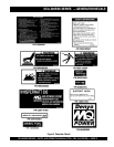
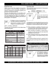
DCA-300SSK — ENGINE OPERATING PANEL
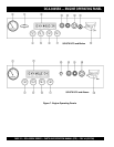
The definitions below describe the controls and functions of
the DCA-300SSK or
DCA-300SSK2
“Engine Operating
Panels”
(Figure 7).
1. Throttle Handle - This handle controls the speed of
the engine (low or high).
2. Tachometer – Indicates engine speed in RPM’s for 60
Hz operation. This meter should indicate 1800 RPM’s
when the rated load is applied. In addition a built in hour
meter will record the number of operational hours that
the generator has been in use.
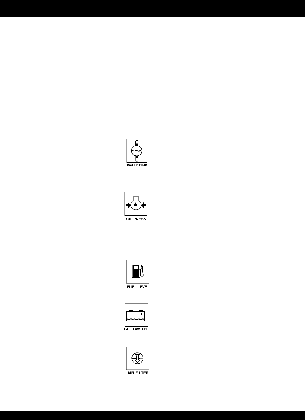
3. Engine Warning Display Module – This module
display’s the following engine failures:
A. Overheat Lamp – This lamp goes ON when
the cooling water temperature rises
abnormally. If the lamp goes ON during
normal operation of the generator, the
emergency shutdown device will stop the
engine automatically.
B. Low Oil Pressure Lamp – During normal
operation of the generator this lamp should
remain OFF. When the
Auto-OFF/Reset
-
Manual switch is set to the “Manual”
position to start the engine, the lamp will
be lit. After the oil pressure rises after start-
up the lamp will go OFF. If this lamp is ever lit (ON)
during normal operation of the generator, the emergency
shutdown device will stop the engine automatically.
C. Low Fuel Level Lamp – When this lamp is
ON, it is time to stop the engine and add
fuel. Remember to let the engine cool before
adding fuel.
D. Low Battery Fluid Lamp – This lamp goes
ON when the battery fluid is low. If this lamp
goes ON during normal operation of the
generator, stop the engine and fill the
battery with distilled water to the specified
level.
E. Clogged Air Filter Lamp – This lamp goes
ON when the air filter is clogged. If this lamp
goes ON during normal operation of the
generator, stop the engine and replace the
air filter.
4. Oil Pressure Gauge – During normal operation this
gauge be should read in the “GREEN” zone. When
starting the generator the oil pressure mar read a little
bit higher, but after the engine warms up the oil pressure
should return to the green zone.
5. Water Temperature Gauge – During normal operation
this gauge be should read in the “GREEN” zone.
6. Charging Ammeter Gauge – Indicates the current
being supplied by the engine’s alternator which provides
current for generator’s control circuits and battery
charging system.
7. Fuel Gauge - Indicates amount of diesel fuel available.
8. Pre-Heat Lamp – Indicates that the glow plugs of the
diesel engine are hot and the engine is ready to be
started.
9. Pre-Heat Button – Press and hold this button until the
preheat lamp is lit (ON).
10. Emergency Stop Button – Push this button inward to
stop the engine in the event of an emergency. DO NOT
use this button as a means of stopping the engine.
11. Ignition Switch (Up to S/N3701673) – Four position
switch,
pre-heat
,
stop
,
run
and
start
. Insert ignition
key to start and stop engine.
12. Battery Switch – This switch should be set to the ON
position during normal operation. When the engine has
been stop, place this switch in the OFF position. DO
NOT turn this switch during normal operation, it could
cause damage to the electrical equipment.
13. Engine Speed Switch (S/N3701674~) – Changes
the speed of the engine rpm’s (low or high).