


8
3
Attaching
Support
Bracket &
Bracket
Assembly
Model Series 700
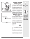
NOTE:
If the grass collection
system is removed for
any reason, it is not
necessary to remove the
support brackets from the
tractor.
IMPORTANT:
There are two holes in
the clevis pin. Be sure
to insert the hairpin
clip in the upper hole
to properly secure the
bracket assembly to the
hitch plate.
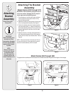
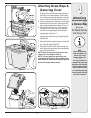
Assembling Support
Brackets
Model Series 700
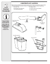
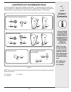
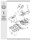
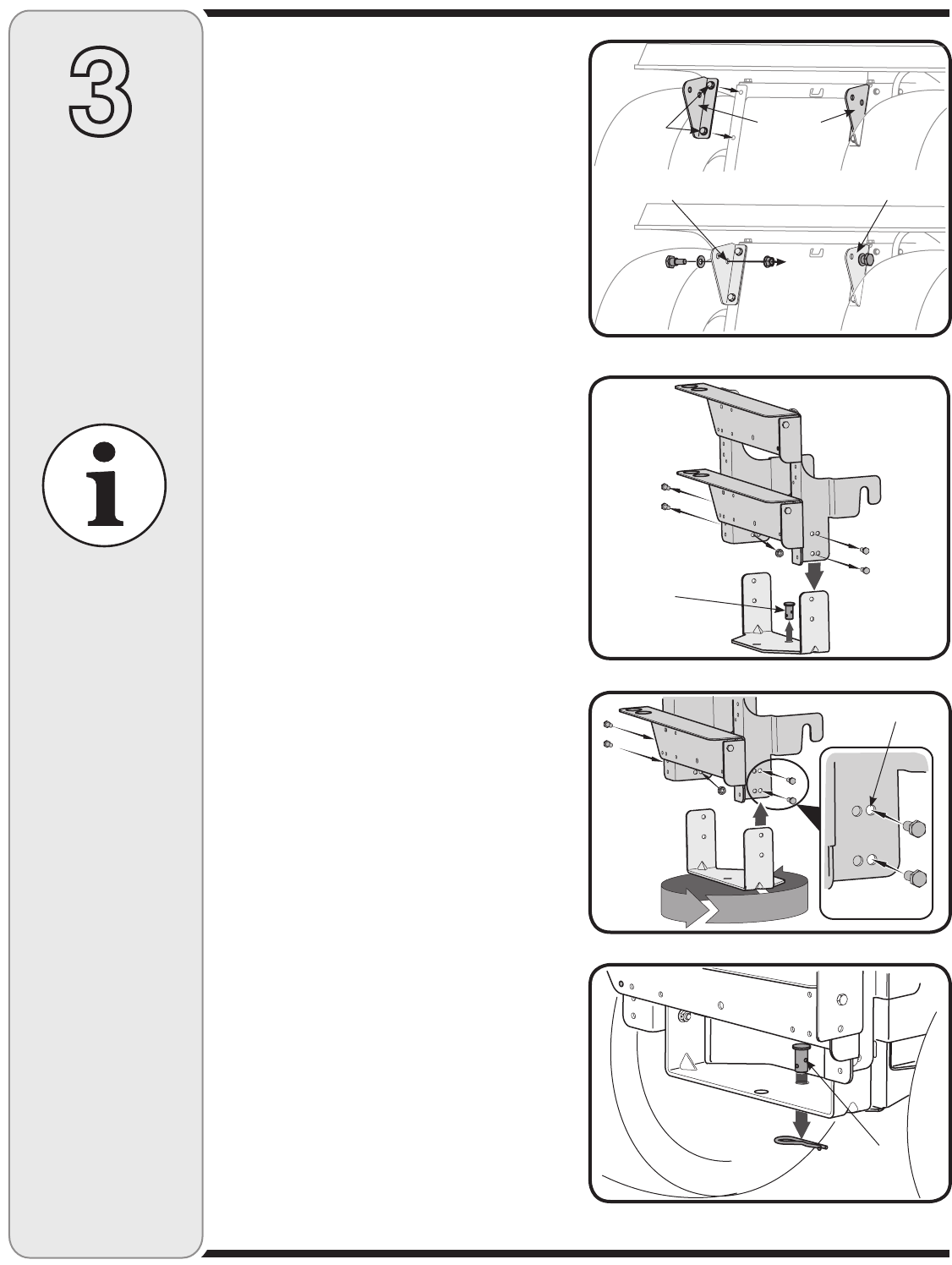
1. Locate the four self-tapping screws supplied in your
hardware pack (D from Figure 4). Attach the right
hand grass catcher support bracket (F1 from Figure
4) using two of the supplied screws in position
as shown in Figure 13. Place the left hand grass
catcher support bracket (F2 from Figure 4) in position
and secure with the other two screws.
5. Insert a shoulder bolt (C in Figure 4) through a bell
washer, (B in Figure 4) and insert the bolt through
the Inner hole (closest to the frame) on the outside
of the support bracket. Secure with a nut (A in Figure
4). See Figure 13 for details. Repeat on other side.
NOTE: If the grass collection system is removed for
any reason, it is not necessary to remove the support
brackets from the tractor.
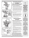
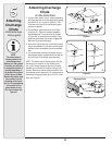
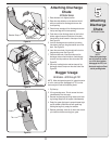
Attaching The Bracket
Assembly
1. Remove the two nuts and screws on each side of the
mounting bracket holding the hitch plate.
See Figure 14.
2. Rotate the hitch plate 180° from its original position.
Re-insert the four bolts through mounting bracket
and hitch plate frame and secure with nuts removed
earlier. Use the inner holes (closest to the mounting
hooks) on the mounting bracket. Refer to Figure 15.
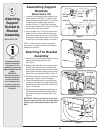
3. Remove the hairpin clip and clevis pin from the hitch
plate as seen in Figure 14. Save the hardware.
4. Position the hooked ends of the mounting bracket
assembly to the outside of the support bracket and
over the shoulder bolts on both sides. Refer back to
Figure 11 for reference.
5. Reinsert the clevis pin through the aligned holes in
both the bracket assembly and the hitch plate and
secure with the hairpin clip removed earlier. See
Figure 16.
IMPORTANT: There are two holes in the clevis pin.
Be sure to insert the hairpin clip in the upper hole to
properly secure the bracket assembly to the hitch
plate.
Figure 13
Figure 15
Figure 16
Figure 14
Outside of Bracket
Inner Hole
Inner holes
Upper Hole
Clevis Pin
Support
Bracket
Self tap
screws