


7
Figure 10
Figure 9
3
Attaching
Support
Bracket &
Bracket
Assembly
Model Series 650
through 699
IMPORTANT:
Before assembly, place
the tractor on a firm,
level surface, disengage
the PTO, turn off tractor
engine and set the park-
ing brake.
NOTE:
If the grass collection
system is removed for
any reason, it is not
necessary to remove the
support brackets from the
tractor.
IMPORTANT:
There are two holes in
the clevis pin. Be sure
to insert the hairpin
clip in the upper hole
to properly secure the
bracket assembly to the
hitch plate.
NOTE:
For some tractor
models, this clevis
pin is too large. Use a
smaller clevis pin in
its place with the same
hairpin clip.
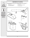
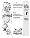
Assembling Support
Brackets
Model Series 650 through 699
IMPORTANT: Before assembly, place the tractor on
a firm, level surface, disengage the PTO, stop the
tractor engine and set the parking brake.
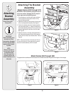
1. Remove the top four self-tapping screws from the rear
of the lawn tractor. See Figure 7 on the previous page.
2. Place the right hand grass catcher support bracket (F1
from Figure 4), in position, with the wide end on top and
the narrow end pointing down as shown in Figure 8.
3. Secure the support bracket to the tractor frame with two
self-tapping screws earlier removed. Refer to Figure 8.
Repeat on the other side using part F2 from Figure 4.
NOTE: If the grass collection system is removed for
any reason, it is not necessary to remove the support
brackets from the tractor.
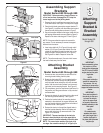
4. Insert a shoulder bolt (C in Figure 4) through a bell
washer, (B in Figure 4) and insert the bolt from the
outside of the bracket through the outer hole on the
support bracket. Secure with a nut (A in Figure 4).
See Figure 8 for details. Repeat on other side.
NOTE: The reference above to “the outer hole” means
the hole furthest away from the frame.
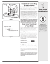
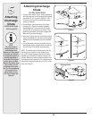
Attaching Bracket
Assembly
Model Series 650 through 699
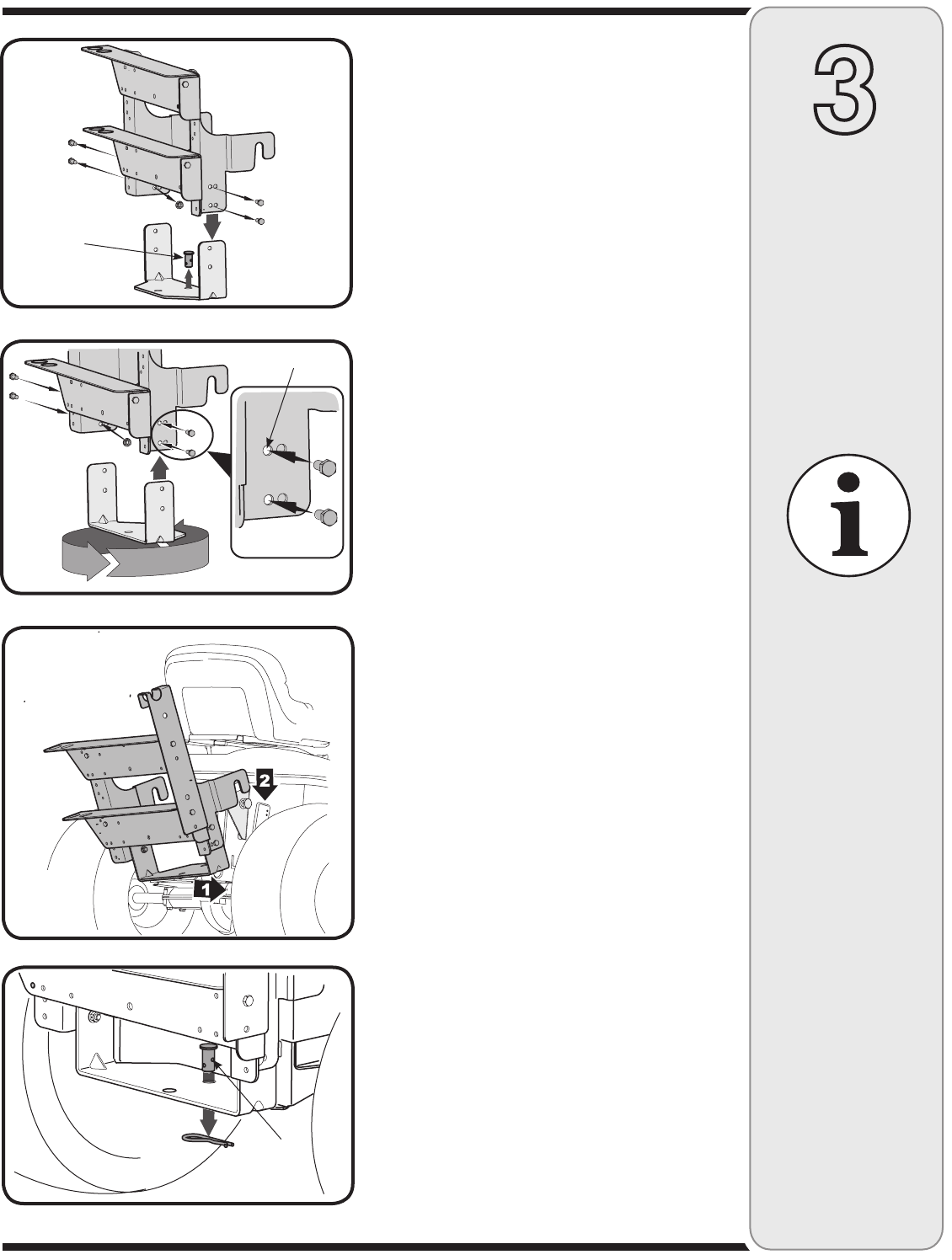
1. Remove the two nuts and bolts on each side of the
mounting bracket holding the hitch plate.
2. Rotate the hitch plate 180° from its original position.
Re-insert the four bolts through mounting bracket
and hitch plate frame and secure with nuts removed
earlier. Use the outer holes (furthest from the mount
-
ing hooks) on the mounting bracket. See Figure 10.
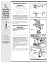
3. For convenience, pivot the seat forward and leave it in
that position until the grass collector is fully mounted
and assembled.
4. Remove the hairpin clip and clevis pin from the rear of
the mounting bracket assembly. See Figure 9.
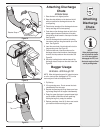
5. Position the hooked ends of the mounting bracket
assembly to the outside of the support brackets and
over the shoulder bolts just installed on both sides of
the tractor frame. See Figure 11.
6. Reinsert the clevis pin through the aligned holes in
both the bracket assembly and the hitch plate and
secure with the hairpin clip removed earlier. See
Figure 12 for reference.
IMPORTANT: There are two holes in the clevis pin.
Be sure to insert the hairpin clip in the upper hole to
properly secure the bracket assembly to the hitch plate.
NOTE: For some tractor models, this clevis pin is
too large. Use a smaller clevis pin (E in Figure 4) in
Outer holes
Figure 11
Figure 12
Upper Hole
Clevis Pin