


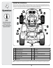
18
Deck Gauge Wheel Adjustment
NOTE: The deck gauge wheels are an anti-scalp feature
of the deck and are not designed to support the weight of
the cutting deck.
The deck gauge wheels should neither contact the
ground, nor be high off the ground, when the deck is
moved to the desired height setting. If you change your
cutting height during the mowing season, the gauge
wheels should be checked and adjusted as necessary.
Adjust the gauge wheels as follows:
• Place the tractor on a smooth, flat surface and move
the deck to the desired mowing height using the deck
lift lever.
• Check gauge wheels distance from the flat surface
below. If the gauge wheels contact the ground, they
must be raised. If the gauge wheels are higher than
1/2" above the ground, they should be lowered.
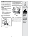
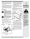
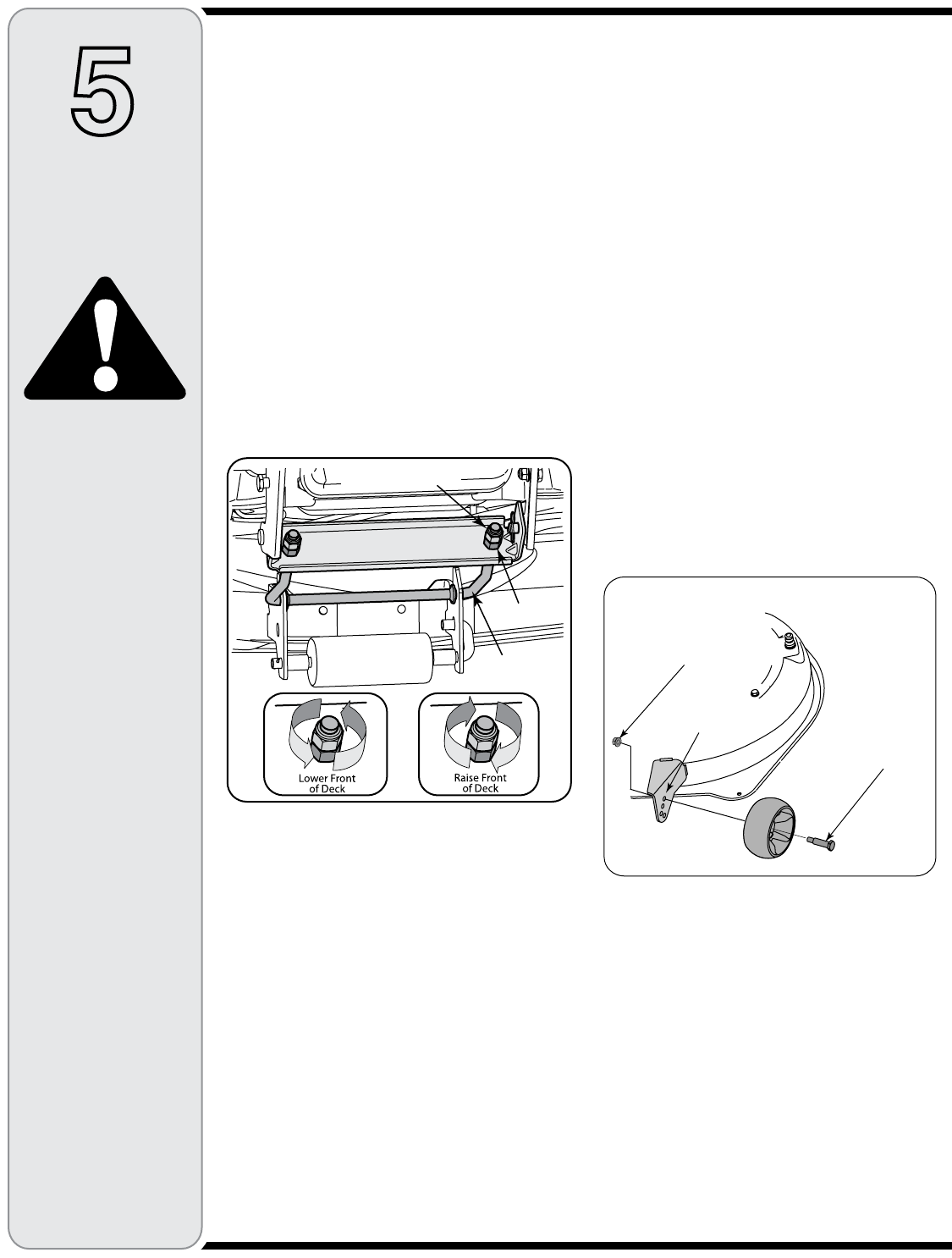
• Remove the shoulder bolt securing one of the front
ball wheels to the front index bracket. Reposition the
ball wheel to align with the one of four index holes
that places the wheel 1/4" to 1/2" above the ground.
Secure the ball wheel to the index bracket with the
shoulder bolt. Note the index hole used and secure
the other ball wheel in the same position. See Figure
12.
Front To Rear Leveling
The front of the cutting deck is supported by an adjust-
able front deck hanger rod. This rod can be adjusted
to set the front to rear pitch of the deck. The front of the
deck should be between 1/4-inch and 3/8-inch lower than
the rear of the deck. Adjust if necessary as follows:
1. With the tractor parked on a firm, level surface, move
the deck to the mid height position (third or fourth
notch) using the deck lift lever. Rotate the blade
nearest the discharge chute so that it is parallel with
the tractor frame.
2. Measure the distance from the front of the blade tip to
the ground and the rear of the blade tip to the ground.
The front measurement taken should be between 1/4”
and 3/8” less than the rear measurement. Determine
the approximate distance necessary for proper adjust-
ment and proceed, if necessary, to the next step.
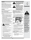
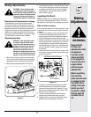
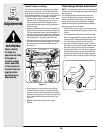
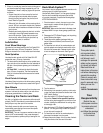
3. Working at the front of the tractor, loosen the two hex
lock nuts at the front of the deck hanger rod. Thread
the lock nuts away from the hex nuts behind them.
See Figure 11.
4. Using a wrench, turn the inner hex nuts clockwise
to raise the front of the deck, or counterclockwise to
lower the front of the deck. Adjust the hex nuts evenly
so that the deck hanger rod is at the front of both slots
in the hanger bracket on the front of the deck. See
Figure 11.
5. Retighten the two hex lock nuts when properly
adjusted.
5
Making
Adjustments
WARNING
Never attempt
to make any
adjustments while
the engine is
running, except
where specified
in the operator’s
manual. Stop the
engine before
performing any
adjustments.
Hex Lock Nut
Hex Nut
Front Deck
Hanger Rod
Figure 11
Figure 12
Shoulder
Bolt
Lock Nut
Front Index
Bracket