


8
WARNING: Over-tightening the cable
may prohibit the auger and drive from
disengaging and compromise the safety
of the snow thrower. Do NOT overtighten
the cable.
NOTE: Refer to Auger Control Test in the Operation
Section prior to operating your snow thrower. Read and
follow all instructions carefully and perform all
adjustments to verify your snow thrower is operating
safely and properly.
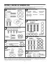
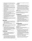
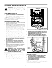
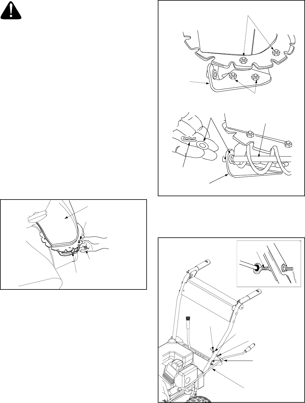
Attaching Chute Assembly
(Hardware Group F)
• Place chute assembly over chute opening, with the
opening in the chute assembly facing the front of
the unit.
• Place chute flange keepers beneath lip of chute
assembly, with the flat side of chute flange keeper
facing downward. See Figure 7.
• Insert hex bolt up through chute flange keeper and
chute assembly and secure with hex lock nut. After
assembling all three chute flange keepers, tighten
all nuts and bolts securely. Do not overtighten.
NOTE: Lock nuts cannot be threaded onto a bolt by
hand. Tighten with two 7/16” or adjustable wrenches.
Figure 7
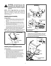
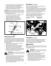
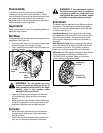
Attaching Chute Directional Control
(Hardware Group G)
• Loosen the two hex nuts which secure the lower
chute directional control support bracket to the
snow thrower housing. See Figure 8.
• Place one flat washer over the end of the chute
directional control, then insert the end of the chute
directional control into the hole in the plastic
bushing on the chute bracket. Place second flat
washer on chute directional control, and secure
with hairpin clip. See Figure 8.
Figure 8
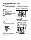
• Thread one hex nut onto the eyebolt on the chute
directional control assembly until there is at least
two inches of threads showing between the nut and
the eyebolt head. See Figure 9.
Figure 9
Chute Assembly
Hex Bolt
Hex Lock Nut
Chute Flange
Keeper
Hex Bolts &
Hex Lock Nuts
Lower
Chute
Directional
Control
Bracket
Hex Nuts
Hairpin Clip
Flat
Washers
Chute Directional
Control
Chute Directional
Control Bracket
Eye Bolt
Cupped
Washer
Hex Nut
2” of thread
Hex Nut
Chute Directional
Control