


7
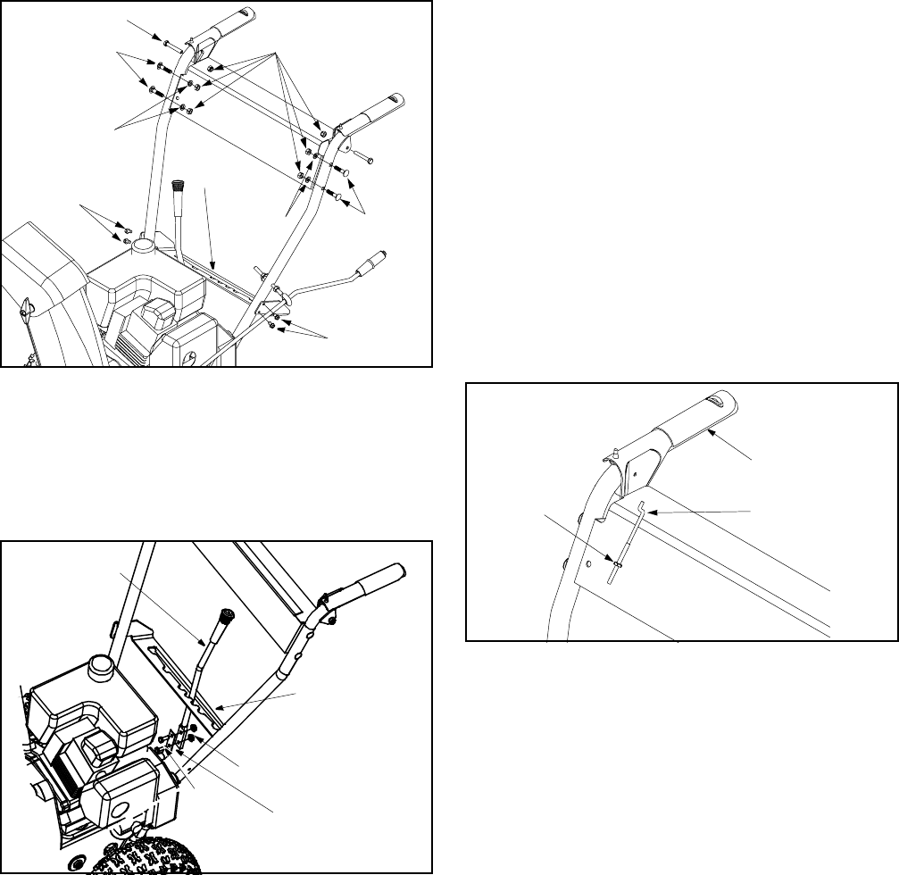
• Secure each clutch grip with a hex bolt threaded
from the outside of each handle and tighten with
hex lock nut under handle panel. See Figure 3.
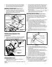
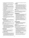
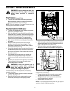
Attaching Handle Panel (Hardware Group C)
• Position the handle panel between handles and
insert two carriage bolts on each side and secure
with lock washers and hex patch nuts.
See Figure 4.
Figure 4
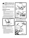
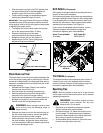
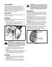
Attaching Speed Selector Plate
(Hardware Group D)
• Assemble the speed selector plate to the outside
of the handles. Secure using two self-tapping
screws on each side. See Figure 5.
Figure 5
Attaching Shift Lever
• Insert the shift lever through slot in the speed
selector plate. See Figure 5.
NOTE: The bend in the lever should be towards the
operator.
• Secure shift lever to the shift lever spring using two
hex bolts (G) and hex lock nuts (H). Tighten both
bolts finger tight. At this point the shift lever and
shift lever spring are not against each other. As you
tighten the bolts and nuts with two wrenches, these
will pull together.
• Tighten all hardware assembled to this point. Make
sure that clutch grips are moving freely.
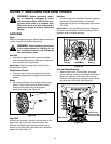
Attaching Control Cables (Hardware Group E)
Z fittings with jam nuts might be already inserted in
each control lever (on the handle panel) at the factory.
To attach the cables to the Z fittings, proceed as
follows:
NOTE: Two extra jam nuts are included in the hardware
pack in the event either are lost during shipping.
• If Z fittings are not already attached, thread hex
nuts onto the “Z” fittings and insert “Z” fitting into
hole in clutch grips. See Figure 6.
• Route the left cable between engine and speed
selector plate and then between handle panel and
clutch lever pivot rod before threading onto the left
“Z” fitting.
• Assemble the right cable in the same manner.
• Both cables should have minimal slack, but not
tight.
Figure 6
• If Z fittings are already attached, thread the jam
nuts all the way up each of the Z fittings, toward the
handle panel.
• Make certain all cables are in the grooves of the
cable roller guides in the lower rear of the unit, one
on each side. Refer to Figure 2.
• Thread the coupling end of the cable onto the
threaded portion of the Z fitting until the rubber
bumper (located on the underside of the clutch
lever) only lightly contacts the upper handle.
IMPORTANT:
The cable should have very little slack, but
should NOT be tight. An overtightened cable may
prohibit the auger and drive from disengaging.
• Once properly adjusted, tighten the jam nut against
the coupling end of the cable to lock it in position.
Carriage Bolts
Self-Tapping
Screws
Self-Tapping
Screws
Hex Lock Nuts
Lock Washer
Lock
Washer
Carriage
Bolts
Speed
Selector
Plate
Hex Cap Screw
Hex Lock Nuts
Hex
Bolts
Shift Lever
Spring
Speed Selector
Plate
Shift Lever
“Z” Fitting R
Jam Nut
Clutch Grip