6
SECTION 3: ASSEMBLING YOUR SNOW THROWER
NOTE: References to right or left side of the snow
thrower are determined from behind the unit in the
operating position. The “operator’s position” is defined
as standing directly behind the snow thrower, facing the
handle panel.
Unpacking
• Remove staples or break glue on top flaps of the
carton. Remove any loose parts included with unit
(i.e., operator’s manual, etc.).
• Cut corners of the carton and lay ends down flat.
Remove packing material.
• Roll unit out of carton. Check carton thoroughly for
loose parts before discarding.
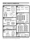
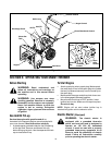
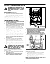
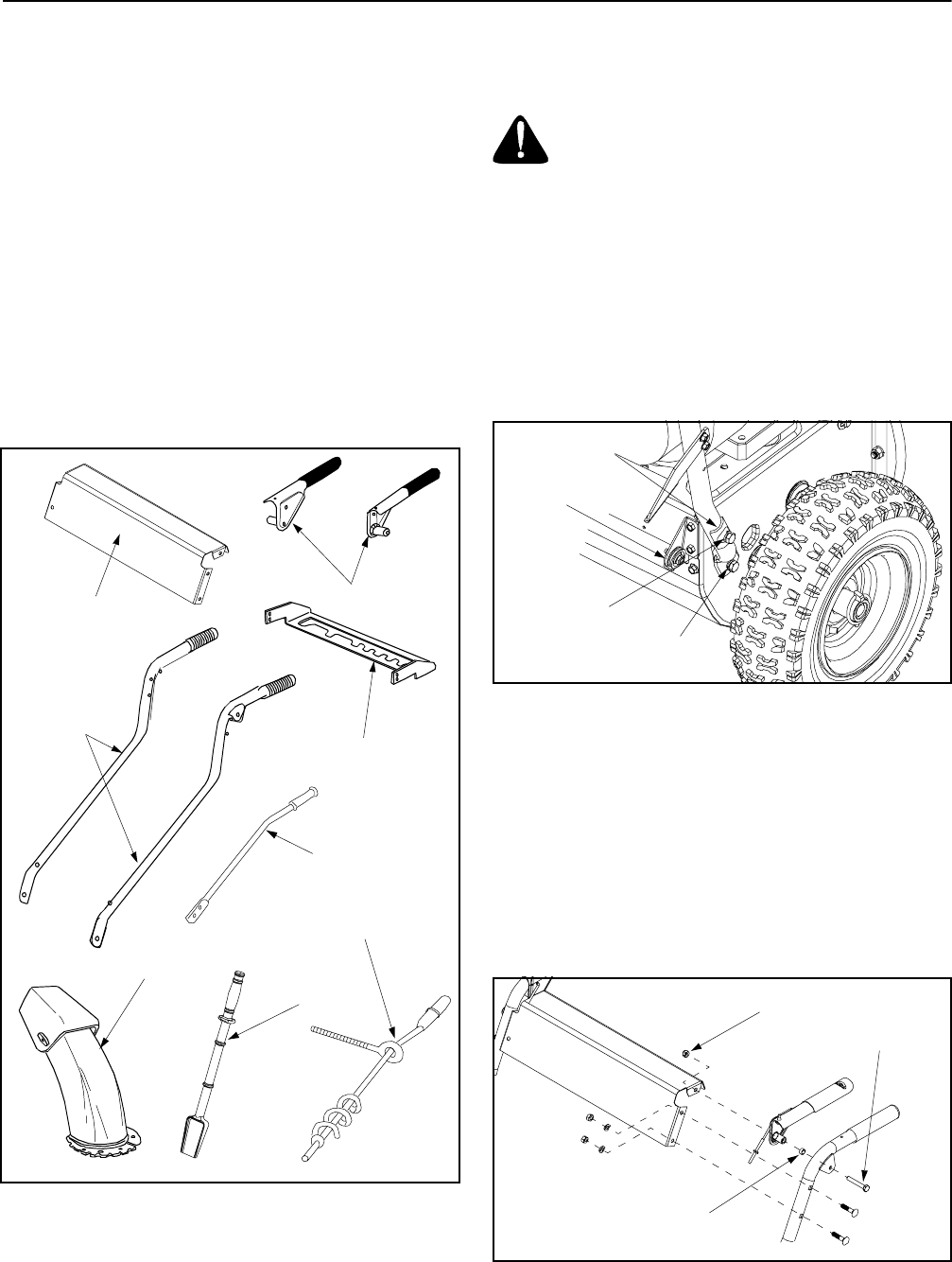
Loose Parts In Carton
Figure 1
*This item is fastened with a cable tie to the rear of
the Auger Housing at the factory.
Before Assembly
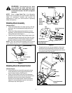
WARNING: Disconnect the spark plug
wire and ground it against the engine to
prevent unintended starting.
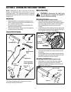
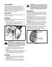
Attaching Handles (Hardware Group A)
• Place right handle in position against the snow
thrower so that the flat side of the handle is against
the frame. Align the bottom hole on the handle to
the corresponding hole on the snow thrower
housing.
• Insert hex bolt and lock washer through these holes
to secure the handle to the snow thrower housing.
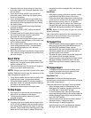
Do not tighten at this time. See Figure 2.
Figure 2
• Attach the left handle in the same manner and do
not tighten.
• Place saddle washer over upper holes on handles
and secure to the frame with lock washers and hex
bolts. Do not tighten now. See Figure 2.
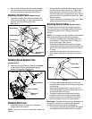
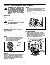
Attaching Clutch Grips (Hardware Group B)
• Slide spacer on each end of the clutch grip and
place the clutch grip in position on the each
respective handle. Clutch grips must sit on top of
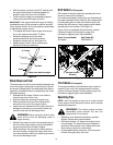
the handles. See Figure 3.
Figure 3
Clutch Grips
Handle Panel
Speed Selector
Plate
Handles
Shift Lever
Chute
Assembly
Chute Directional
Control Assembly
Clean-out
Tool*
Saddle Washer
Hex Bolt &
Lock Washer
Hex Bolt &
Lock Washer
Cable Roller
Guide
Spacer
Hex Bolt
Hex Lock Nut


