


13
SECTION 6: MAKING ADJUSTMENTS
WARNING: Never attempt to make any
adjustments while the engine is running,
except where specified in operator’s
manual.
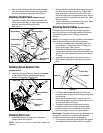
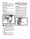
Tire Pressure (Pneumatic Tires)
• The tires are overinflated for shipping purposes.
Before operating check tire pressure and reduce
pressure to between 15psi and 20 psi.
NOTE: If the tire pressure is not equal in both tires, the
unit may pull to one side or the other.
Traction Control & Shift Lever
• To check the adjustment of the traction control and
shift lever, proceed as follows:
• With the engine off, move the shift lever all the way
forward to fifth (5) position. With the traction control
released, push the snow thrower forward. The unit
should move forward freely. Then engage the
traction control grip. Wheels should stop turning.
• Now release the traction control grip and push the
unit again.
• Move the shift lever back to the fast reverse
position, then all the way forward again. There
should be no resistance in the shift lever, and the
wheels should keep turning.
• If you feel resistance when moving the shift lever or
the wheels stop when they should not, loosen the
jam nut on the traction control cable and unthread
the cable one turn.
• If the wheels do not stop when you engage the
traction control grip, loosen the jam nut on the
traction control cable and thread the cable in one
turn.
• Recheck the adjustment and repeat as necessary.
Tighten the jam nut to secure the cable when
correct adjustment is reached.
WARNING: Drain the gasoline out of
snow thrower engine, place a piece of
plastic film under the gas cap to avoid
spillage before beginning the job.
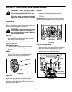
To test further for correct adjustment, if necessary,
proceed as follows:
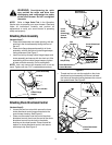
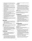
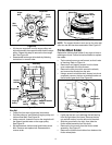
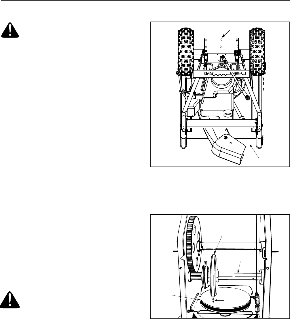
• Tip the snow thrower so that it rests on the auger
housing. See Figure 14.
• Remove the frame cover underneath the snow
thrower by removing six self-tapping screws.
Figure 14
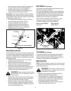
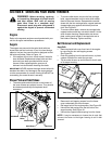
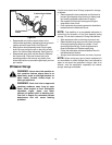
• With the traction control is released, there must be
clearance between the friction wheel and the drive
plate in all positions of the shift lever.
• With the traction control is engaged, the friction
wheel must contact the drive plate. See Figure 15.
Figure 15
If adjustment is necessary.
• Loosen the jam nut on the traction control cable
and thread the cable in or out as necessary.
• Retighten the jam nut to secure the cable when
correct adjustment is reached.
• Reassemble the frame cover.
NOTE: If you placed plastic film under the gas cap, be
certain to remove it before operating.
Frame Cover
Auger Housing
Friction
Wheel
Gear Shaft
Drive
Plate
Gap