


FX2N-5A Special function block Buffer Memory (BFM) 7
7-56
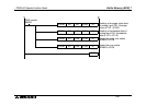
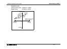
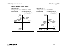
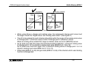
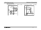
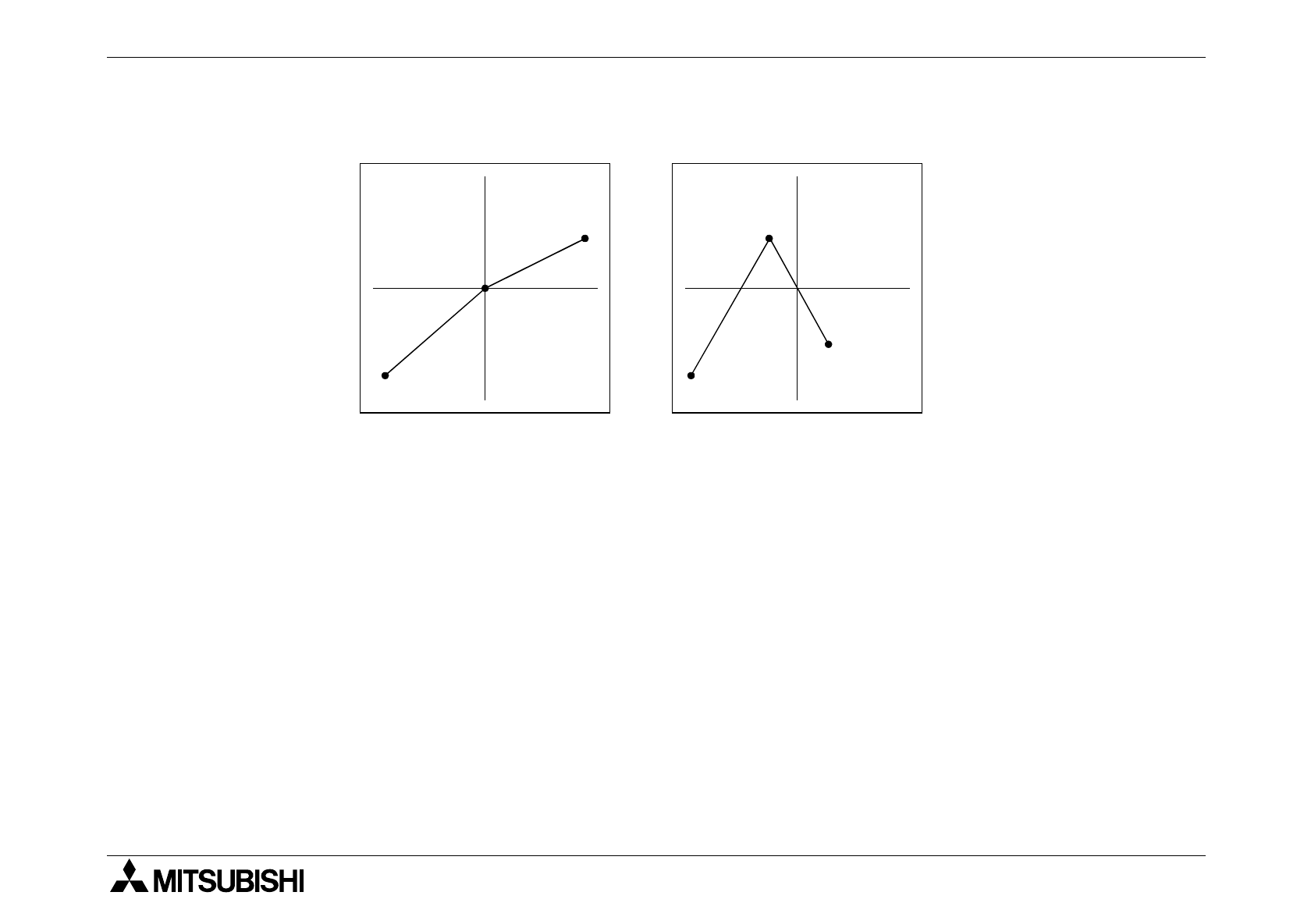
• When using K0 as a change point setting value, the subsequent change point value must
the larger in both the "Digital value" and "Analog scale value". (See figure 2.)
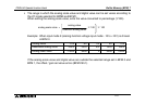
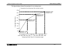
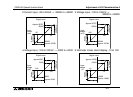
• The I/O to be entered for each channel should fall within the range of the analog scale value
of Change point 1 (minimum value) to that of Change point 3 (maximum value).
When an analog value outside this range is entered, scale over error (BFM 28) occurs.
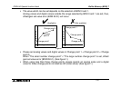
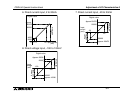
• As for scale over less than lower limit and disconnection detection, a minimum analog value
of change point 1 to 3 is stored in analog input value (BFM 6 to 9, 10 to 13).
As for scale over more than upper limit, a maximum analog value of change point 1 to 3 is
stored in analog input value (BFM 6 to 9, 10 to 13).
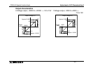
• Offset data (BFM 41 to 45) and gain data (BFM 51 to 55) of the channel which uses Scaling
function is disregarded.
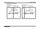
Digital
value
Analog
scale
value
Change
point 1
Change
point 3
Change
point 2
Digital
value
Analog
scale
value
Change
point 1
Change
point 3
Change
point 2
✔✗
(Available) (Not available)
Figure 2