


FX2N-5A Special function block Wiring 5
5-3
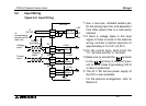
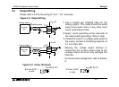
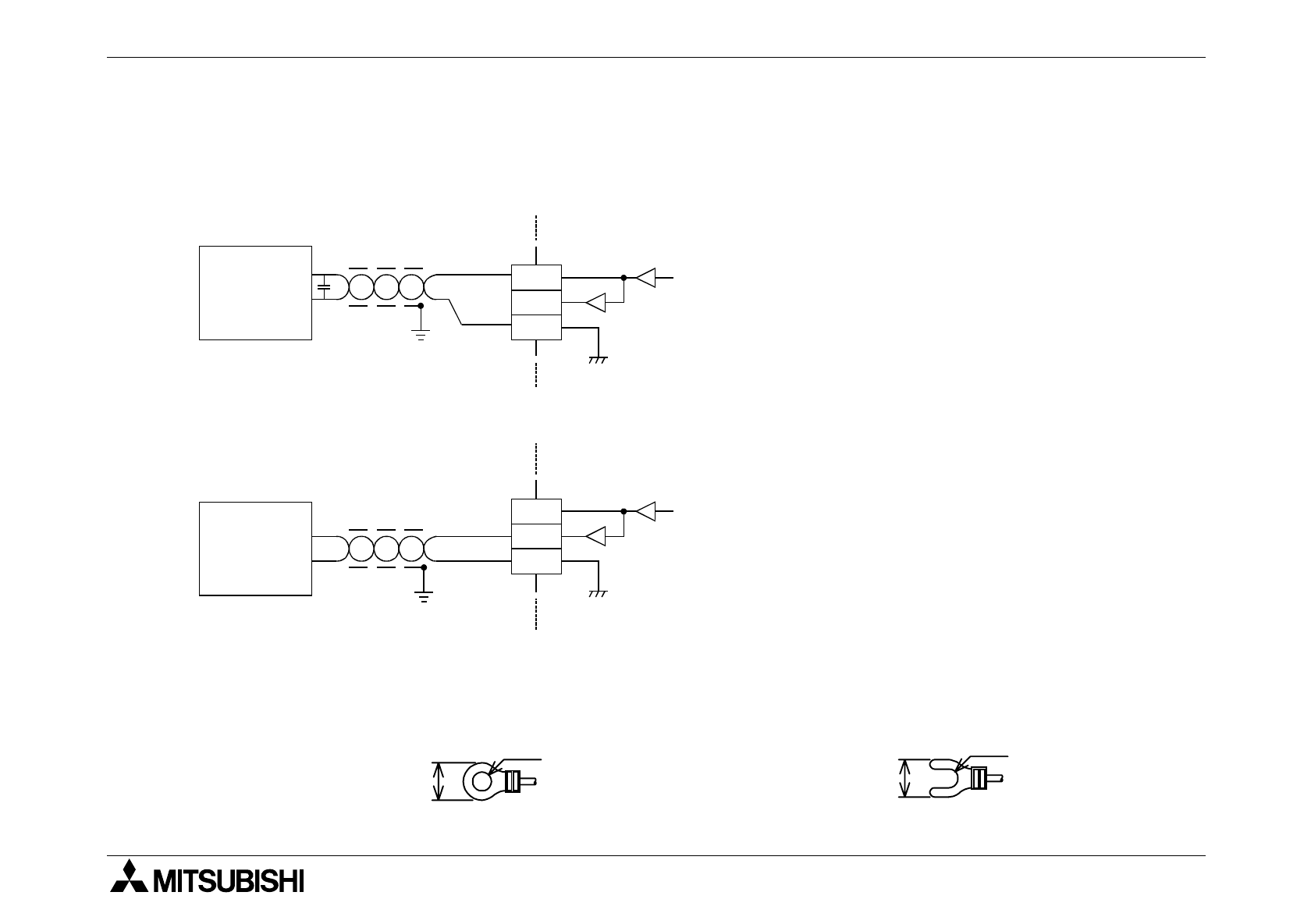
5.3 Output Wiring
Please refer to 5.2 for the wiring for "24+", "24-" terminals.
Figure 5.3: Output Wiring
*1 Use a twisted pair shielded cable for the
analog output. This cable should be wired
away from power lines or any other lines
which could induce noise.
*2 Apply 1-point grounding at the load side of
the output cable (grounding: 100
Ω
or less).
*3 If electrical noise or a voltage ripple exists at
the output, connect a smoothing capacitor of
0.1 to 0.47
µ
F, 2 5 V.
- Shorting the voltage output terminal or
connecting the current output load to the
voltage output terminal may damage the
FX
2N
-5A.
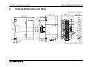
- For the terminal arrangement, refer to Section
2.
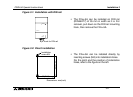
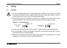
Figure 5.4: Crimp Terminals
Voltage output
V+
VI-
I+
OUT
*1
Shielded cable
Current output
V+
VI-
I+
OUT
Inverter,
etc.
Recorder,
etc.
*2
*1
Shielded cable
*2
FX
2N
-5A
FX
2N
-5A
*3
N.C.
6.2 mm (0.24" )
or less
For M3 (0.12")
6.2 mm (0.24")
or less
For M3 (0.12")