


FX2N-5A Special function block Buffer Memory (BFM) 7
7-38
7.2.25 BFM 51 to BFM 54 Analog Input Gain data (READ/WRITE)
Input Gain data: Analog input value when the digital value is 16000 (or 1000 in mode 4).
The offset data and the gain data for each channel can be set independently.
The set value is written in "mV" for voltage input (-10V/+10V), in "
µ
A" for current input and in
10
µ
V units for
±
100mV input.
The values of BFM 51 to 54 are stored non-volatile in the internal EEPROM. There is a safety
function to protect the internal EEPROM from being destroyed by accidentally writing the same
value continuously to a BFM.
Initial offset/gain value (Unit: mV for voltage input,
µ
A for current input and 10
µ
V for
±
100mV
input)
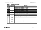
Note: This table is not applicable for modes 9 to B (see Scaling function settings.)
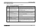
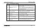
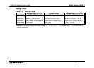
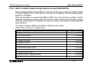
Table 7.8: Initial offset/gain input value
Input mode
(BFM 0)
0
(-10
to
+10V)
1
(4
to
20mA)
2
(-20
to
+20mA)
3
(-100 to
+100mV)
4
(-100
to
+100mV)
Initial offset value 0 4000 0 0 0
Initial gain value 5000 unit:mV 12000 unit:
µ
A 10000 unit:
µ
A 5000 unit:10
µ
V 5000 unit:10
µ
V
Input mode
(BFM 0)
5
Voltmeter mode
(-10
to
+10V)
6
Amperemeter mode
(4
to
20mA)
7
Amperemeter mode
(-20
to
+20mA)
8
Voltmeter mode
(-100
to
+100mV)
Initial offset value 0 fixed 0 fixed 0 fixed 0 fixed
Initial gain value
16000 fixed
unit:mV
16000 fixed
unit:
µ
A
16000 fixed
unit:
µ
A
16000 fixed
unit:10
µ
V