


FX2N-5A Special function block Buffer Memory (BFM) 7
7-12
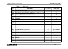
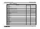
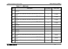
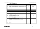
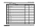
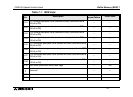
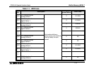
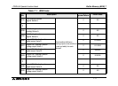
7.2 Details of buffer memories
7.2.1 BFM 0 input mode specification (READ/WRITE)
BFM 0 specifies the input mode of CH1 to CH4. The BFM consists of a 4-digit hexadecimal
code, where one digit is assigned to each input channel. The range for each digit is a Hex
value between 0 to F.
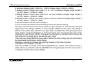
The highest digit corresponds to input ch4, whereas the lowest digit corresponds to input ch1.
The meaning of the digits is as follows:
0: Voltage input mode (-10 to +10 V) (Display range -32000 to +32000)
1: Current input mode (4 to 20 mA) (Display range 0 to +32000) if current is less than 2mA, a
range error alarm will be set in BFM 28
2: Current input mode (-20 to +20 mA) (Display range -32000 to +32000)
3: Voltage input mode (-100 to +100 mV) (Display range -32000 to +32000)
4: Voltage input mode (-100 to +100 mV) (Display range -2000 to +2000)
5: Voltmetor display mode (-10V to + 10V) (Display range -10000 to +10000)
6: Amperemeter display mode (4mA to +20mA) (Display range 2000 to +20000 = 2mA to
20mA) if current is less than 2mA, a range error alarm will be set in BFM 28
7: Amperemeter display mode (-20mA to +20mA) (Display range -20000 to +20000)
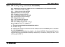
BFM#0
H
{{{{
CH1
CH2
CH3
CH4