


44
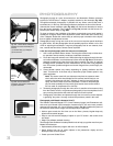
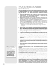
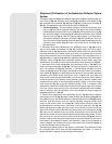
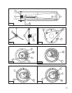
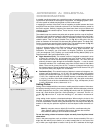
Alignment (Collimation) of the Newtonian Reflector Optical
System
The optical systems of Newtonian Reflector telescopes include the following parts: pri-
mary mirror (1, Fig. 34); secondary mirror (2, Fig. 34); secondary mirror-holder (3, Fig.
34
); secondary mirror-vanes (4, Fig. 34) and (1, Fig. 35); primary mirror-tilt screws (5,
Fig. 34
). The telescope’s image is brought to a focus at (6, Fig. 34).
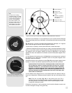
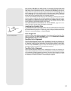
1.
Confirm alignment - To confirm optical alignment look down the focuser draw-
tube
(1, Fig. 37) with the eyepiece removed. The edge of the focuser drawtube
frames reflections of the primary mirror (
2, Fig. 37), the secondary mirror (3, Fig.
37
), the three (“spider”) vanes (4, Fig. 37) holding the secondary mirror, and the
observer’s eye (
5, Fig. 37). With the optics properly aligned, all of these reflec-
tions appear concentric (centered), as shown in
Fig. 37. Any deviation from con-
centricity of any of these telescope parts with the eye requires adjustments to the
secondary mirror-holder (
Fig. 35) and/or the primary mirror cell (Fig. 36, as
described below.
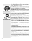
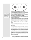
2.
Secondary mirror-vane adjustments: If the secondary mirror (1, Fig. 38) is left or
right of center within the drawtube (
2, Fig. 38), slightly loosen the 3-vane adjust-
ment/lock knobs (1, Fig. 35) located on the outside surface of the main tube and slide
the entire secondary mirror-holder system up or down in the slotted holes of the main
tube until the secondary mirror is centered in the drawtube. If the secondary mirror (
1,
Fig. 38
) is above- or below-center within the drawtube, thread inward one of the adjust-
ment/lock knobs (
1, Fig. 35) while unthreading another of these knobs. Only make
adjustments to two knobs at a time until the secondary mirror appears as in
Fig. 39.
3.
Secondary mirror-holder adjustments: If the secondary mirror (1, Fig. 39) is cen-
tered in the focuser drawtube (
2, Fig. 39), but the primary mirror is only partially vis-
ible in the reflection (
3, Fig. 39), the three “+” (Phillips head) secondary mirror-tilt
screws (
2, Fig. 35) should be slightly unthreaded to the point where the secondary
mirror-holder (
3, Fig. 35) can rotate about its axis parallel to the main tube. Grasp the
secondary mirror-holder (avoid touching the mirror surface!) with your hand and
rotate it until, looking through the drawtube, you can see the primary mirror centered
as well as possible in the reflection of the secondary mirror. With the rotation of the
secondary mirror-holder at this best-possible position, thread in the three Phillips
head screws (
2, Fig. 35) to lock the rotational position. Then, if necessary, make
adjustments to these three Phillips head screws to refine the tilt-angle of the second-
ary mirror, until the entire primary mirror can be seen centered within the secondary
mirror’s reflection. With the secondary mirror thus aligned the image through the
drawtube appears as in
Fig. 40.
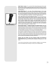
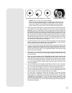
4.
Primary mirror adjustments: If the secondary mirror (1, Fig. 40) and the reflection
of the primary mirror (
2, Fig. 40) appear centered within the drawtube (3, Fig. 40), but
the reflection of your eye and the reflection of the secondary mirror (
4, Fig. 40) appear
off-center, then the primary mirror tilt requires adjusting, using the Phillips head
screws of the primary mirror cell (
3, Fig. 36). These primary mirror-tilt screws are
located behind the primary mirror, at the lower end of the main tube. See
Fig. 36.
Before adjusting the primary mirror-tilt screws, first unscrew by several turns (use
either a hex wrench or pliers) the three hex-head primary mirror lock screws (
2, Fig.
36
) which are also located on the rear surface of the primary mirror cell and which
alternate around the cell’s circumference with the three Phillips head screws. Then by
trial and error turn the primary mirror Phillips head tilt screws (
3, Fig. 36) until you
develop a feel for which way to turn each screw to center the reflection of your eye in
the drawtube. (An assistant is helpful in this operation.) With your eye centered as
shown in
Fig. 37, turn the three hex head primary mirror lock screws (2, Fig. 36) to
re-lock the tilt-angle of the primary mirror.
The telescope’s optical system is now aligned, or collimated. This collimation should
be re-checked from time to time, with small adjustments (per steps 1, 2, and/or 3,
above) effected as required to keep the optics well-aligned.