


12
knob to a firm feel. Replace the safety cap.
Note: If the counterweight ever slips, the safety cap (23, Fig. 1d) prevents
the counterweight from sliding entirely off the shaft. Always leave the
safety cap in place when the counterweight is on the shaft.
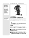
6. Set the latitude: Setting the latitude is easier if it is set before you attach the opti-
cal tube to the assembly. Locate the latitude dial (
28, Fig. 1d); note that there is
a triangular pointer above the dial located on the mount. The pointer is not fixed;
it moves as the mount moves.
Determine the latitude of your observing location. See APPENDIX C: LATITUDE
CHART
, page 57, for a list of latitudes, or check an atlas. Move the latitude T-han-
dle screws in order to move the mount until the pointer points to your latitude. The
two T-handle screws work in a "push - pull" operation—as you tighten one, loosen
the other. When the pointer points at your latitude, tighten both screws until they
make contact with the mount.
At your observing site, set up the telescope assembly so that the tripod leg below
the Fine Azimuth Control Knobs (
27, Fig. 1c) approximately faces North (or
South in the Southern Hemisphere). Model SC-8 users, see APPENDIX E, page
62.
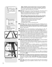
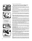
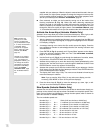
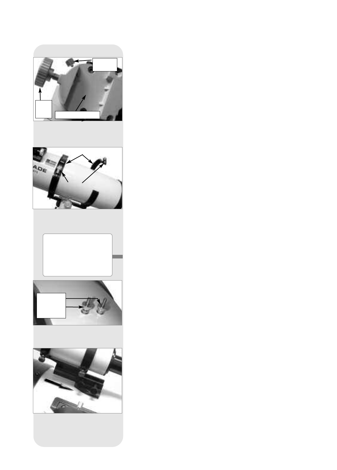
7.
Attach the cradle assembly to the mount: Remove the optical tube from the
cradle and slide the cradle assembly (11, Fig. 1a) onto the cradle mounting slot.
See
Fig. 7. The rounded base of the cradle assembly fits into the rounded por-
tion of the mounting slot. Tighten both the cradle locking knob and the secondary
locking knob to a firm feel.
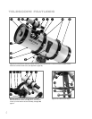
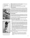
8. Position optical tube: Unscrew the cradle ring lock knobs (13, Fig. 1a) and open
the cradle rings. While firmly holding the optical tube (
10, Fig. 1a), position it onto
the cradle rings (14, Fig. 1a) with the mid-point of the optical tube’s length lying
roughly in the center of the cradle ring assembly. Point the tube so that the front
end (this end comes shipped with the dust cover (9, Fig. 1a) over it) is oriented
as depicted in
Fig. 1a. Then close the cradle rings (14, Fig. 1a) over the optical
tube. Loosely tighten the cradle ring lock knobs just to hold the tube securely in
place until you balance it. See BALANCING THE TELESCOPE, page 13.
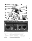
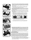
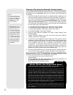
9. Attach viewfinder bracket: Newtonian models (Fig. 9a): Locate the viewfinder
bracket screws (
Fig. 9a) and remove the nuts from the screws. Slide the holes in
the viewfinder bracket over the viewfinder bracket screws. Replace the nuts and
tighten to a firm feel only.
Attach viewfinder tube: Back off the viewfinder collimation screws (5, Fig. 1b)
and slide the viewfinder tube into the bracket. Orient the viewfinder eyepiece as
depicted in
Fig. 1b. Tighten the collimation screws to a firm feel. See ALIGNING
THE VIEWFINDER, page 14.
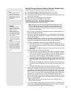
Attach viewfinder bracket: Achromatic refractor, Schmidt-Newtonian and
Schmidt-Cassegrain models (15, Fig. 1b
and Fig. 9b ): Slide the track on the
bottom of the viewfinder bracket into the slot in the viewfinder mounting assem-
bly (which is already attached to the tube). To secure the viewfinder to the mount-
ing assembly, tighten the two thumbscrews to a firm feel only.
Attach viewfinder tube: Back off the viewfinder collimation screws (5, Fig. 1b)
and slide the viewfinder tube into the bracket. Point the viewfinder eyepiece
toward the focuser assembly. See Fig. 10b. Tighten the collimation screws to a
firm feel. See
ALIGNING THE VIEWFINDER, page 14.
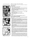
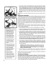
10. Insert the eyepiece: Schmidt-Newtonian and Newtonian models (Fig. 10a):
Lift to remove the dust cap from the eyepiece holder on the focuser assembly.
Set the dust cap aside in a safe place and replace it when you have finished
observing to protect the eyepiece assembly. Back off the eyepiece thumbscrews
(
1, Fig. 1a) and insert the supplied SP 26mm eyepiece (3, Fig. 1a) into the the
eyepiece holder. Tighten the holder thumbscrews to a firm feel to secure the eye-
piece.
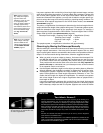
Insert the eyepiece: Achromatic refractor and Schmidt-Cassegrain models
(Fig. 10b):
Lift to remove the dust cap from the eyepiece holder on the focuser
assembly. Set the dust cap aside in a safe place and replace it when you have
Fig. 7: Attach cradle to base mount-
ing slot and tighten locking knobs.
Fig. 8: Place optical tube in rings
and loosely tighten cradle ring lock
knobs.
Fig. 9a: Viewfinder assembly,
Newtonian reflector models.
Viewfinder
Mounting
Screws and
Nuts
Cradle Rings
Lock
Knobs
Cradle
Lock
Knob
Secondary
Lock Knob
Cradle Assembly Slot
Fig. 9b: Viewfinder assembly, refrac-
tor and Schmidt-Newtonian and
Schmidt-Cassegrain models models.
Note: Model SC-8 users:
After completing step 6,
refer to APPENDIX E, page
62, step 1, for information
on how to attach the SC
optical tube to the mount.