


11
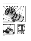
As you unpack your telescope, carefully note the following parts. The assembly is
shipped in separate boxes.
Telescope Assembly
■ Equatorial mount with polar alignment finder
■ Heavy duty, adjustable aluminum tripod with leg braces, three tripod leg lock
knobs, and a captive mount locking knob
■ Complete optical tube assembly including primary mirror with dust cover and a
rack-and-pinion focuser and eyepiece holders for both 1.25" and 2" eyepiece
holders, tube cradle assembly with two rings and two lock knobs
■ Super Plössl (SP) 26mm eyepiece
■ Counterweight and counterweight shaft. The 8" and 10" models include extra
counterweights.
■ 8 x 50mm (all models, except N-6EC Newtonian) or 6 x 30mm (N-6EC
Newtonian only)
viewfinder.
■ Factory-mounted dual electronic motor drive assembly
■ Autostar handbox, detachable coil cord, or Electronic Controller
■ Battery pack and holder
Accessories
■ Hex keys, T-Adapter (included with Schmidt-Newtonian models only)
How to Assemble Your Telescope
The giftboxes contain the optical tube assembly and the tripod with the equatorial
mount. The accessories are located within compartments custom-cut into the styro-
foam block inserts.
1.
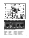
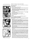
Remove the components from the giftboxes: Remove and identify the tele-
scope’s equipment. Refer to Figures 1a through 1f for images of the parts and
the overall assembly of your telescope. When removing the tripod from the gift-
box, hold the assembly parallel (horizontal) to the ground or the inner tripod leg
extensions will slide out as they are not locked in place.
2.
Adjust the tripod legs. Spread the tripod legs as far as they will open. See Fig. 3.
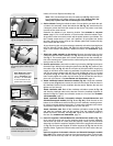
3.
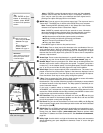
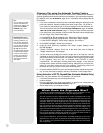
Attach the spreader bar to the tripod with shaft: Thread the tension knob onto
the shaft (see Fig. 4). Place the spreader bar over the T-handle shaft. Slide the
bushing, the wide open side facing downward, onto the shaft as far as it will go
(
Fig. 5a). Then slide the shaft up through the tripod mounting base (37, Fig. 1c).
Above the mount, snap the e-clip into the second, narrower precut slot (see Fig.
5a) of the shaft (Fig. 5b).
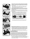
4. Attach mount to tripod base: Place the mount over the tripod mounting base
(
37, Fig. 1c) and onto the shaft, with the protrusion on top of the tripod's base
positioned between the fine azimuth control knobs (27, Fig. 1d). See Fig. 5c. If
necessary, back off the azimuth control knobs wide enough for protrusion to fit
between them.
Tighten the T-handle to a firm feel. This attachment keeps the tripod and the tel-
escope mount securely in place. Then line up the spreader bar braces so that
they are each touching one of the tripods legs. Tighten the tension knob (
39, Fig.
1c) to a firm feel. When you wish to collapse the tripod, loosen the tension knob
and move the braces off the legs. You do not need to remove the T-handle/shaft.
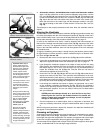
5.
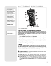
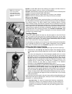
Attach the counterweight(s) to the counterweight shaft: Place the counter-
weight shaft base (20, Fig. 1d) over the threaded end of the shaft (22, Fig. 1d).
Thread the shaft and base assembly into the hole beneath the Dec. setting circle
as depicted in
Fig. 6.
Look through the hole in the counterweight and note the pin blocking the hole. Tilt
the counterweight slightly and the pin moves out of position, clearing the hole. If the
pin does not move, unscrew the counterweight lock knob slightly until the pin moves.
Unscrew the safety cap (
23, Fig. 1d) from the shaft. Holding the counterweight
(21, Fig. 1d) firmly in one hand, slip the counterweight to approximately the mid-
point of the counterweight shaft (22, Fig. 1d). Tighten the counterweight lock
GETTING STARTED
Fig. 6: Attach counterweight
assembly.
Shaft
Safety
Cap
Lock
Knob
Counterweight
Shaft
Base
Dec. Setting Circle
Fig. 5a: Slide bushing over shaft.
Fig. 5b: Snap e-clip all the way onto
shaft above mount (shown partially
attached).
Fig. 5c: Attach the mount to the
tripod.
Protrusion
Place mount over
shaft with bushing
and c-clip.
Fine
Azimuth
Control
Knobs
Second
slot
Bushing
E-clip
Second
slot