


12
GETTING STARTED
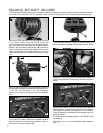
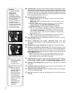
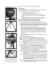
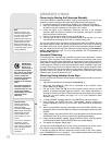
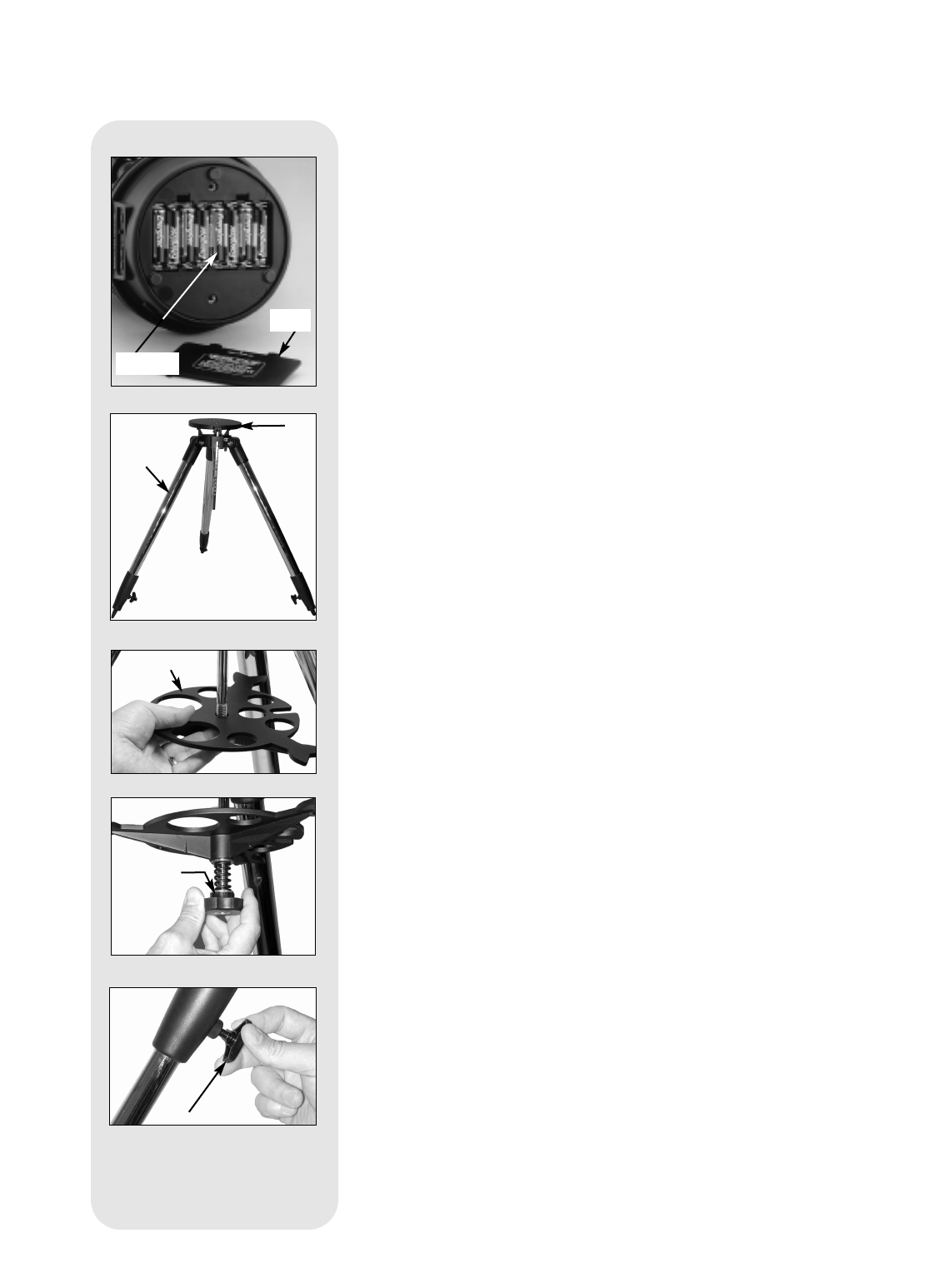
Fig. 5: Battery installation.
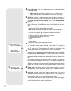
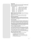
Fig. 6: Spread tripod legs.
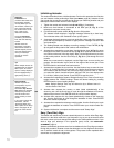
Fig. 7: Slide spreader on rod.
Parts Listing
Getting the telescope ready for first observations requires only a few minutes. When
first opening the packing box, note carefully the following parts:
• The ETX Astro Telescope with fork mount system.
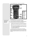
• #497 Autostar handbox with coil cord.
• One or more eyepieces, packed in plastic storage containers.
• Hex-wrench, packed with the instruction manual. See
MAINTENANCE,
page 45.
• #884 Deluxe Field Tripod; two attachment knobs; spreader tray with sepa-
rate spring, washers (2) and tension knob; leg extension lock knobs.
How to Assemble Your Telescope and Tripod
Assembly of the ETX telescope requires eight AA-size (user-supplied) batteries.
1. Remove the ETX telescope from its packaging and place it on a sturdy surface.
Place the ETX on its side and remove the battery compartment cover from the
underside of the drive base. Insert eight (user-supplied) AA-size batteries into the
battery compartment oriented as shown in the battery compartment. Replace the
cover and return the telescope to an upright position.
Caution: Use care to install batteries as indicated by the diagrams in the
battery compartment. Follow battery manufacturer's precautions. Do not
install batteries backwards or mix new and used batteries. Do not mix
battery types. If these precautions are not followed, batteries may
explode, catch fire or leak. Improperly installed batteries void your Meade
warranty. Always remove the batteries if they are not to be used for a long
period of time.
Note: Autostar does not require batteries; the telescope’s batteries
supply power to Autostar.
2. Assemble the #884 Deluxe Field Tripod:
Step a: Spread the tripod (1, Fig. 6) legs apart to a fully open position.
Step b: Slide the spreader tray (2, Fig. 7) onto the central threaded rod.
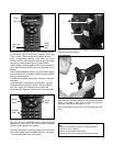
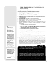
Step c: Slide a washer, followed by the spring, another washer and the
tension knob (3, Fig. 8) onto the threaded rod. Tighten the tension knob
to a firm feel.
Step d: Adjust the height of the tripod by loosening the leg lock knobs (4, Fig. 9)
and adjusting the height of the inner leg extensions. Then retighten the lock
knobs.
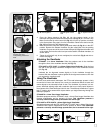
3. Mount your telescope in the altazimuth (alt/az) mode. If you wish to mount your
telescope in the equatorial mode, see EQUATORIAL ALIGNMENT, page 51.
Note: Throughout this manual, you will notice the term "Alt/Az," or more
properly, altazimuth.This term is frequently used to refer to altitude or the
up-and-down vertical movement of the telescope). Azimuth refers to the
side-to-side horizontal movement of the telescope.
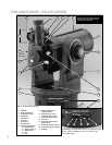
Step e: Loosen the latitude control latch (6, Fig.10) and lift up the tilt-plate (5, Fig.
10) so that you can easily access the underside of the plate. Relock the
latitude control latch, so the assembly doesn't slip while you are attaching
the telescope.
Step f: Line up the mounting hole (7, Fig. 11) on the base of the telescope
marked "High Latitude Leg" with the attachment knob (
8, Fig. 11) that is
closest to the latitude control bar (
9, Fig. 11). Line up the other
mounting hole with the attachment knob at the bottom of the tilt-plate.
Thread both attachment knobs into the base of the telescope. Tighten to
a firm feel only. (
See Fig. 12.)
Step g: Unlock the latitude control latch (10, Fig. 13) and lower the tilt-plate until
it is level (push the tilt-plate down until it stops; this is the level
position). Lock the latitude control latch.
Batteries
Cover
ᕡ
ᕢ
ᕢ
ᕤ
Fig. 8: Tension knob assembly.
Fig. 9: Adjust tripod height.
ᕣ