


10 11
4 - FUEL AND LUBRICATION
4-1. FUEL
Use regular g
rade unleaded gasoline mixed with Genuine
Factory Parts 40:1 custom 2-cycle engine oil for best
results. Use mixing ratios in Section 4-3.
Never use straight gasoline in your unit.This will cause
permanent engine damage and void the manufactur-
er’s warranty for that product. Never use a fuel mixture that
has been stored for over 90 days.
If 2-cycle lubricant other than Genuine Factory Parts
Custom Lubricant is to be used, it must be a premium
grade oil for 2-cycle air cooled engines mixed at a 40:1
ratio. Do not use any 2-cycle oil product with a recommend-
ed mixing ratio of 100:1. If insufficient lubrication is the
cause of engine damage, it voids the manufacturer’s
engine warranty for that occurrence.
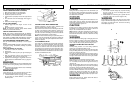
4-2. MIXING FUEL
Mix fuel with Genuine Factory Parts brand 2 cycle oil in an
approved container. Use mixing table for correct ratio of fuel
to oil. Shake container to ensure thorough mix.
Lack of lubrication voids engine warranty.
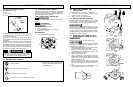
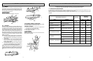
4-3.FUEL AND LUBRICATION SYMBOLS
FUEL MIXING TABLE
4-4.RECOMMENDED FUELS
Some conventional gasolines are being blended with oxy-
genates such as alcohol or an ether compound to meet
clean air standards. Your McCulloch engine is designed to
operate satisfactorily on any gasoline intended for automo-
tive use including oxygenated gasolines.
4-5.CHAIN AND BAR LUBRICATION
Always refill the chain oil tank each time the fuel tank is
refilled. We recommend using Genuine Factory Parts
Chain, Bar and Sprocket Oil, which contains additives to
reduce friction and wear and to assist in the prevention of
pitch formation on the bar and chain.
Gasoline and Oil
Mix 40:1
Oil Only
5 - OPERATING INSTRUCTIONS
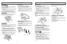
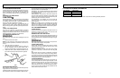
5-1. ENGINE PRE-START CHECKS
WARNING
Never start or operate the saw unless the bar and chain are
proper
ly installed.
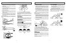
1. Fill the fuel tank (A) with correct fuel mixture (Figure 5-
1A).
2. Fill the oil tank (B) with correct chain and bar oil (Figure
5-1A).
3. Be certain the CHAIN BRAKE
®
is disengaged (C)
before starting unit (Figure 5-1A).
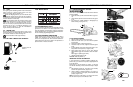
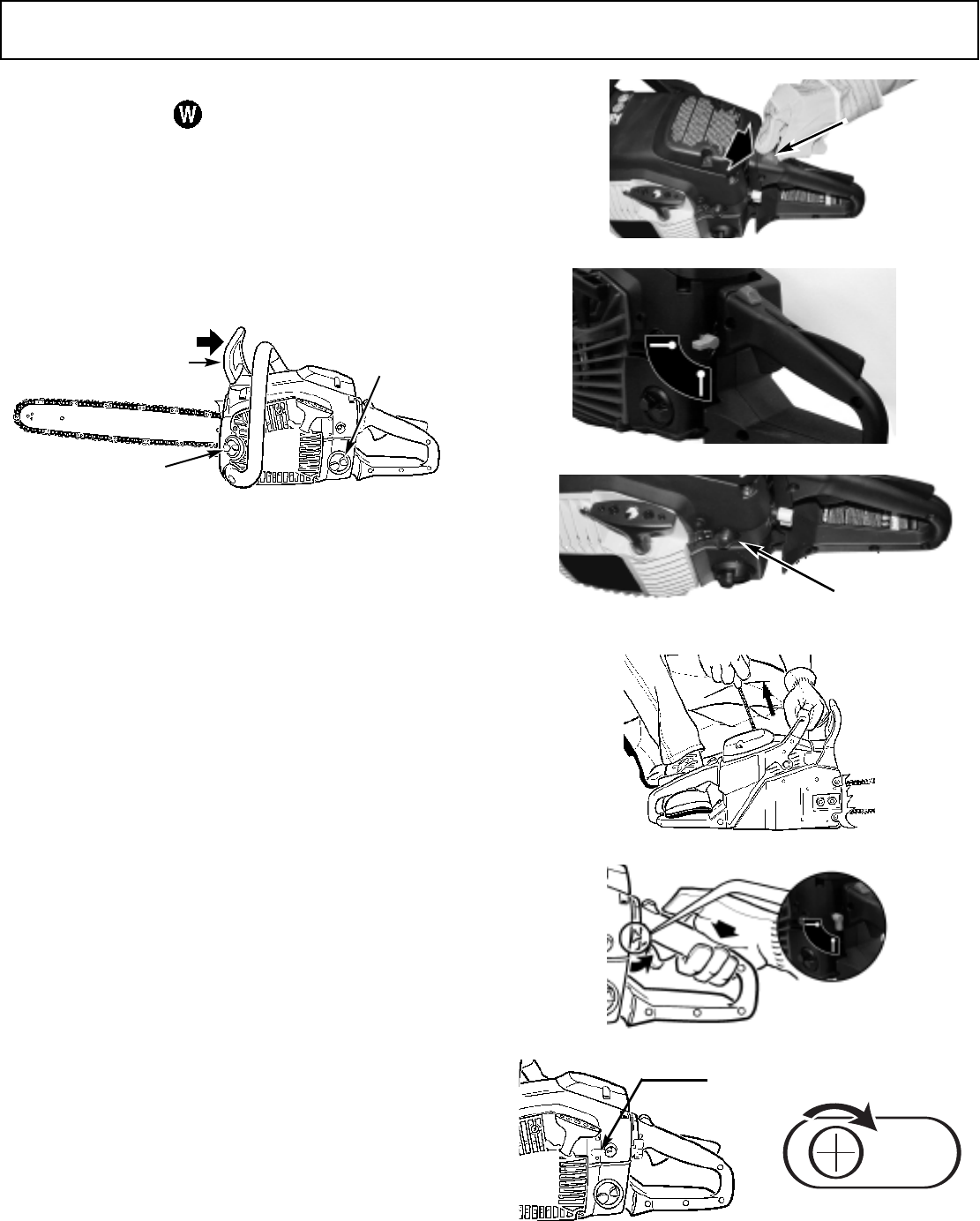
5-2.TO START ENGINE
1. Slide the STOP switch down (Figure 5-2A).
2. Rotate the choke lever up to the horizontal position
(Figure 5-2B).
3. Pump primer bulb 10 times (Figure 5-2C).
4. Pull starter rope 4-6 times, engine should start (Figure
5-2D).
5. If engine failed to start, rotate choke lever down to ver-
tical position then repeat step 4 (Figure 5-2D).
6. When engine starts, warm up 10 sec. Then depress
safety/throttle trigger.The automatic choke will disen-
gage
when tr
igger is pulled (Figure 5-2E).
7. Release throttle trigger for idle.
TO STOP: Slide stop switch up.
IMPOR
T
ANT IDLING INFORMA
TION
In some cases due to operating conditions (altitude, tem-
per
ature etc.) y
our chain sa
w may need a slight adjustment
to the idle speed.
After warm up - See the section 5-2, step 8 - If unit does
not Idle after restarting 2 times, follow these steps to adjust
idle.
1. Idle adjustment access (A) - the symbol "T" (for throttle)
is belo
w the adjustment hole (Figure 5-2F).
2. Using a Phillips or slotted screwdriver - turn screw 1/4
to 1/2 tur
n clockwise (to the right). Unit should then idle
properly (Figure 5-2G).
NOTE: If chain turns while idling - turn screw back to the
left until chain stops and unit continues to idle.
5-1A
C
A
B
5-2A
D
5-2B
5-2C
D
Horizontal position
Vertical position
5-2D
5-2E
A
utomatic
A
B
5-2F
5-2G
A