


d. Set the “POLARITY” switch to either WIRE FEED
DC+ or WIRE FEED DC- as required by the
electrode being used.
e. Set the “RANGE” switch to either HIGH, MED or
LOW as required by the process.
f. Set the “WELDING TERMINAL” Control switch to
the “ALWAYS ON” position.
g. Set the “IDLER” switch to the “AUTO” position.
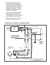
Connection of the LN-7 or LN-8 to the
Ranger 9.
a. Shut off the welder.
b. Connect the LN-7 or LN-8 per the instructions on
the appropriate connection diagram in the rear of this
manual.
c. Set the output control toggle switch to appropriate
position: “CONTROL REMOTE” for LN-8 and LN-7
with K857 attached; “CONTROL AT WELDER” for
LN-7 with no remote voltage control.
d. Set “POLARITY” switch to either WIRE FEED DC+
or WIRE FEED DC-.
e. Set the “RANGE” switch to either HIGH, MED or
LOW as required by the process.
f. Set the “WELDING TERMINALS” Control switch to
the “REMOTELY CONTROLLED” position.
g. Set the “IDLER” switch to the “HIGH” idle position.
Connection of the LN-742 to the Ranger 9
a. Shut off the welder.
b. Connect per the instructions on the appropriate
connection diagram in rear of this manual.
c. Set the output control toggle switch to
“CONTROL AT WELDER” when not using
remote control. When the LN-742 has a K589-1
remote control attached, set output control to
“REMOTE”.
d. Set “POLARITY” switch to either WIRE FEED
DC+ or WIRE FEED DC-.
e. Set “RANGE” switch to either HIGH, MED or
LOW as required by the process.
f. Set the “WELDING TERMINAL” control switch to
“REMOTELY CONTROLLED” position.
g. Set the “IDLER” switch to the “AUTO” position.
-14 -
Connection of the Magnum Spool Gun
and SG Control Module to the Ranger 9
a. Shut off the Welder.
b. Connect per the instructions on the appropriate
connection diagram in the rear of this manual.
c. Set the output control toggle switch to “CONTROL
AT WELDER” when not using remote control.
d. Set the “POLARITY” switch to WIRE FEED DC+.
e. Set the “RANGE” switch to either HIGH, MED or
LOW as required by the process.
f. Set the “WELDING TERMINALS” Control switch to
the “REMOTELY CONTROLLED” position.
g. Set the “IDLER” switch to the “HIGH” idle position.
Remote Output Control
The Ranger 9 has a 6-pin and a 14-pin Amphenol
connector. These connectors are located above the
output studs. The 6-pin connector is intended to be
used with the optional K857 Remote Output Control or
in the case of TIG welding applications, with the Foot
or Hand Amptrol. The 14-pin connector is used to
connect a wire feeder control cable. If the wire feeder
has a built-in power source output control, do not
connect a remote output control to the 6-pin
connector. When remote output control is used, the
output control toggle switch is to be set at “CONTROL
REMOTE”.
High Frequency Generator for TIG
welding applications
The K930-1 TIG Module is an accessory that provides
high frequency and shielding gas control for AC and
DC GTAW (TIG) welding. See IM528 supplied with
the TIG Module for installation instructions.
Note: The TIG Module does not require the use of a
high frequency bypass capacitor. If any other high
frequency accessory is used with the Ranger 9, a
bypass capacitor (Order Kit T12246) must be installed
in the Ranger 9.