


4. Typical conditions of use, i.e., travel speed; rough-
ness of surface on which the trailer will be
operated; environmental conditions; like
maintenance.
5. Conformance with federal, state and local laws.
(
1
)
(
1
)
Consult applicable federal, state and local laws regarding
specific requirements for use on public highways.
PRE-OPERATION SERVICE
READ the engine operating and maintenance instruc-
tions supplied with this machine.
------------------------------------------------------------------------
The Ranger 9 is shipped with the engine crankcase
filled with SAE 10W-30 oil. Check the oil level before
starting the engine. It if is not up to the full mark on
the dipstick, add oil as required. Make certain that the
oil filter cap is tightened securely. Refer to the engine
Operators Manual for specific oil recommendations.
Oil
Fuel
Fill the fuel tank with clean, fresh lead-free gasoline.
The capacity is approximately 9 gallons (34 liters).
Observe the fuel gauge while filling to prevent overfill-
ing.
Battery Connection
This welder is shipped with the negative battery cable
disconnected. Make sure that the Engine Switch is in
the “STOP” position and attach the disconnected
cable securely to the negative battery terminal before
attempting to operate the machine. If the battery is
discharged and does not have enough power to start
the engine, see the Maintenance-Battery section of
this manual for battery charging instructions.
Welding Output Cables
With the engine off, connect the electrode and work
cables to the studs provided. These connections
should be checked periodically and tightened if
necessary.
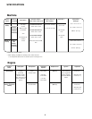
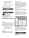
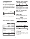
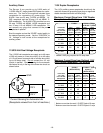
Listed below are copper cable sizes recommended for
the rated current and duty cycle. Lengths stipulated
are the distance from the welder to work and back to
the welder again. Cable sizes are increased for
greater lengths primarily for the purpose of minimizing
cable voltage drop.
TOTAL COMBINED LENGTH OF
ELECTRODE AND WORK CABLES
0-50 Ft.
50-100 Ft.
100-150 Ft.
150-200 Ft.
200-250 Ft.
250 Amps
40% Duty Cycle
2 AWG
2 AWG
1 AWG
1 AWG
1/0 AWG
250 Amps
100% Duty Cycle
1 AWG
1 AWG
1 AWG
1 AWG
1/0 AWG
Location / Ventilation
The welder should be located to provide an unrestrict-
ed flow of clean, cool air to the cooling air inlets and
to avoid heated air coming out of the back of the
welder recirculating back to the cooling air inlets
below the exhaust. Also, locate the welder so that the
engine exhaust fumes are properly vented to an
outside area.
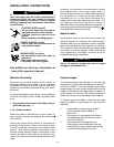
Damage to fuel tank may cause fire or explosion.
Do NO
T drill holes in the Ranger 9 base or weld to
the Ranger 9 base.
------------------------------------------------------------------------
-12 -
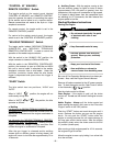
CAUTION
GASOLINE
fuel can cause fire or
explosion.
• Stop engine while fueling.
• Do not smoke when fueling.
• Do not overfill tank.
• Keep sparks and flame away from tank.
• Wipe up spilled fuel and allow fumes to clear
before starting engine.
WARNING
WARNING
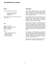
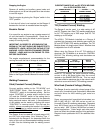
LUBRICATION SYSTEM CAPACITY
(INCLUDING FILTER)
Onan P218 - 1.8 Quarts (1.7 Liters)
Kohler CH20S - 2.0 Quarts (1.9 Liters)