


-13 -
Angle of Operation
Engines are designed to run in the level condition
which is where the optimum performance is achieved.
The maximum angle of operation for the engine is 15
degrees from horizontal in any direction. If the engine
is to be operated at an angle, provisions must be
made for checking and maintaining the oil level at the
normal (FULL) oil capacity in the crankcase.
When operating the welder at an angle, the effective
fuel capacity will be slightly less than the specified 10
gallons.
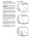
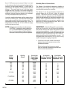
High Altitude Operation
If the Ranger 9 will be consistently operated at
altitudes above 5,000 feet, a carburetor jet designed
for high altitudes should be installed. This will result in
better fuel economy, cleaner exhaust, and longer
spark plug life. It will not
give increased power which
is decreased at higher altitudes. Engine horsepower is
reduced by 3.5% per 1000 feet for altitudes above 377
feet.
High altitude jet kits are available from the engine
manufacturer. Order Onan kit part number 146-0458.
Connection of Lincoln Electric
Wire Feeders
Shut off welder before making any electrical
connections.
------------------------------------------------------------------------
Connection of K428 or K446 LN-25 with
K624-1 42 volt Remote Output Control
Module to the Ranger 9.
Requires K626-xx Control Cable. Provides “cold” electrode
until gun trigger is pressed and also provides voltage control at
the feeder. The K446 LN-25 includes a gas solenoid. See the
appropriate connection diagram in rear of this manual.
a. Shut off the welder.
b. Connect the electrode cable from the LN-25 to the
“ELECTRODE” stud of the welder. Connect the
work cable to the “TO WORK” stud of the welder.
c. Connect the control cable from the LN-25 to the
14 pin amphenol on the Ranger 9.
d. Attach the single lead from the front of the LN-25
to the work using the spring clip on the end of the
lead.
This is a control lead to supply the current to
the wire feeder motor; it does not carry welding
current.
e. Set the “POLARITY” switch to either WIRE FEED
DC+ or WIRE FEED DC- as required by the
electrode being used.
f. Set the “RANGE” switch to either HIGH, MED or
LOW as required by the process.
g. Set the “WELDING TERMINALS” Control switch to
the “REMOTELY CONTROLLED” position.
h. Set the “IDLER” switch to the “AUTO” position.
Connection of the K449 LN-25 to the
Ranger 9.
a. Shut off the welder.
b. Connect the electrode cable from the LN-25 to the
“ELECTRODE” stud of the welder. Connect the
work cable to the “TO WORK” stud of the welder.
c. Attach the single lead from the front of the LN-25 to
work using the spring clip on the end of the lead.
This is a control lead to supply the current to the
wire feeder motor; it does not carry welding current.
Do not operate a Ranger 9 with a high altitude jet installed
at an altitude below 5,000 ft. This will result in the engine
running too lean and result in higher engine temperatures
which can shorten engine life.
------------------------------------------------------------------------
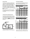
Muffler Relocation
Shut off welder and allow muffler to cool before
touching muffler.
------------------------------------------------------------------------
The Ranger 9 is shipped with the exhaust coming out on
the left side of the machine. The exhaust can be changed
to the opposite side by removing the two screws that hold
the exhaust port cover in place and installing the cover on
the opposite side. (Operating the Ranger 9 without the
cover in place will result in a higher noise level and no
increase in machine output.)
CAUTION
WARNING
WARNING