


B-3
OPERATION
B-3
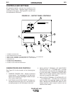
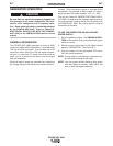
CONTROLS AND SETTINGS
All generator/welder controls are located on the
Output Control Panel. Gasoline engine controls are
mounted on the engine. See Figures B.1 and B.2 and
the explanations that follow.
GENERATOR/WELDER CONTROLS
See Figure B.1 for the location of the following fea-
tures:
1. CURRENT CONTROL DIAL: Adjusts continuous
current output. The amperages on the dial corre-
spond to the average amperages needed for spe-
cific Lincoln welder rods.
2. ELECTRODE SELECTION GUIDE: Provides rec-
ommended electrode type, size, and welder out-
put setting based on the thickness of the work.
3. WELD OUTPUT TERMINAL (TO ELECTRODE
HOLDER) WITH 1/2 - 13 FLANGE NUT: Provides
the connection point for either the electrode hold-
er or the work cable. (Because the POWER-ARC
4000 is an AC output machine, either output ter-
minal can be used for either cable.)
4. WELD OUTPUT TERMINAL (TO WORK) WITH 1/2
- 13 FLANGE NUT: Provides the connection
point for either the electrode holder or the work
cable. (Because the POWER-ARC 4000 is an AC
output machine, either output terminal can be
used for either cable.)
POWER-ARC 4000
POWER ARC
4000
ELECTRODE SELECTION GUIDE
80
90
100
70
AMPS
AMPS
AMPS
AMPS
WARNING
AMPS
125
GENERATOR
8
7
6
5
3
1
2
4
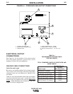
FIGURE B.1 – OUTPUT PANEL CONTROLS
1. CURRENT CONTROL DIAL
2. ELECTRODE SELECTION GUIDE
3. WELD OUTPUT TERMINAL (TO ELECTRODE HOLDER) WITH 1/2 - 13 FLANGE NUT
4. WELD OUTPUT TERMINAL (TO WORK) WITH 1/2 - 13 FLANGE NUT
5. GROUND STUD
6. 20 AMP CIRCUIT BREAKERS (2)
7. 20 AMP, 240 VOLT RECEPTACLE
8. 20 AMP, 120 VOLT DUPLEX RECEPTACLE