


Lexicon
2
Installation
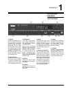
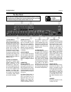
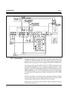
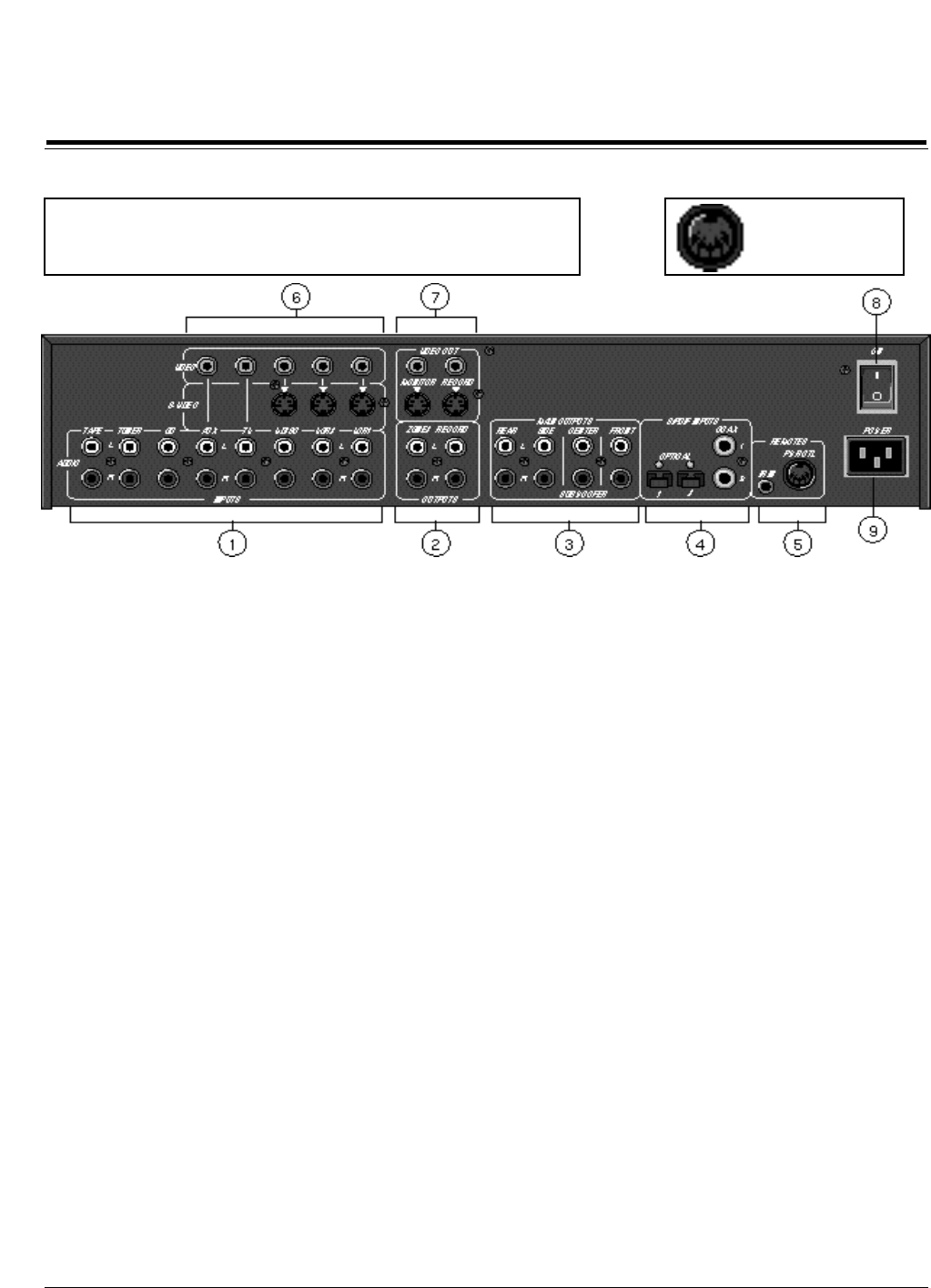
The Rear Panel
CAUTION: Never make or break any connections to the DC-1 with the
rear-panel power ON. Make sure any associated amplifiers are turned
off before turning this master power switch on or off.
1 AUDIO INPUTS
Eight stereo analog audio in-
puts are switched with corre-
sponding video inputs and fed
to the Monitor outputs. Inputs
are nominally labeled as origi-
nating from an audio tape
player, tuner, CD player, an
unspecified auxiliary source,
a TV tuner, a Laser or Video
Disc player, a primary and a
secondary VCR. (Note, in the
On-Screen menus, VCR 1 is
labeled "VCR" and VCR 2 is
labeled "DVD".)
2 ZONE2 and RECORD
Each pair of stereo audio
outputs supplies the same
signal according to the
Record/Zone 2 input selec-
tion. Zone 2 output levels can
be controlled independently
for use with amplifiers and
speakers in another room.
Record can be expanded to
two outputs using standard
Y-connectors. Both outputs
are muted in Standby.
3 MAIN OUTPUTS
Three stereo amplifier out-
puts are provided for front,
side and rear speakers.
Single monaural outputs are
provided for the center
speaker and the subwoofer.
The audio outputs are muted
in Standby.
4 S/PDIF INPUTS
Two coaxial RCA connectors
and two optical connectors
are provided for digital audio
in S/PDIF format at a 44.1or
48kHz ±1000ppm sample
rate.
5 REMOTES:
IR Input, PWR CTL
The IR input is an 1/8" mono
phone jack connector for in-
put of IR data from any indus-
try-standard IR source. Data
is retransmitted by an IR LED
mounted near the front panel
IR receiver.
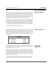
The Power Control port is a
5-pin DIN connector. Pins 1
and 2 are ground, pin 3 is
high when unit is on, low in
standby or Off. High is indi-
cated by either +12VDC or
+5VDC, selectable via an in-
ternal jumper. (Factory con-
figuration is +12V>) Pin 5
can be enabled (high) or dis-
abled (low) for specific input
selections in the Input Con-
figuration menu. See pinout
diagram above.
6 VIDEO INPUTS
Five video input sources are
provided. VCR1, VCR2 and
V-DISC have both compos-
ite and S-Video capabilities.
(S-Video is selected in pref-
erence to the composite sig-
nal.) AUX and TV accept
composite only. Video inputs
are selected based on selec-
tions made in the INPUT
CONFIG menu and fed to
the selected monitor output
jack. Record output jacks can
be selected independently.
7 VIDEO OUTPUTS
RCA (composite) and S-video
connectors are provided for
monitor and record. If an S-
video input is used, both S-
video and composite are
available at each output. If
the video input is composite,
only composite is available at
each output. The monitor
output incorporates the on-
screen video overlay. Unless
RECORD is enabled, the
record output follows the
monitor output selection with-
out the on-screen display fea-
ture. Both outputs are off in
Standby.
8 Power On/Off
Master power switch discon-
nects the AC Mains. This
switch is intended to be left
On during regular use. When-
ever cables are connected or
disconnected, or when the
unit is not going to be used for
an extended period of time,
this switch should be set to
Off.
9 POWER
AC power connector: 3-wire,
10 Amp, IEC 320.
1 = Ground
2 = Ground
3 = Power On
4 = Unused
5 = Trigger (programmable)