


12
Section 2 Operating Instructions
RC45180 & RCM45180 Rotary Cutter 312-382M 7/14/08
Land Pride
Table of Contents
Section 2 Operating Instructions
Operating Check List
In addition to design and configuration of equipment; haz-
ard control and accident prevention are dependent upon
the awareness, concern, prudence and proper training in-
volved in its operation, transport, maintenance and stor-
age of equipment. Before beginning to operate your
Cutter, the following inspection should be performed.
!
WARNING!
The following operating procedures should be carried out by
the tractor operator. Other persons should be cleared of the
area even during cutter setup. cutter operation should be
stopped when in the vicinity of other persons.
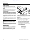
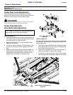
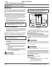
Refer to Figure 2-1:
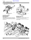
1. Raise the center deck to sufficient height to disengage
the transport link (#1) . Remove the transport link pin
(#2), lower the link arm, then replace the link pin to the
storage position.
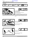
2. Inspect the wing blade carriers and blades prior to
lowering the wings. The wing deck blades may be-
come locked together (overlapped) when the wings
are raised to transport position. Operating the cutter
under such circumstances will result in severe deck vi-
bration. Inspect the wing decks for a locked blade con-
dition prior to power-on operation. Use a pry bar or
other tool to separate the blades if necessary.
3. The automatic wing latches on each wing must be re-
leased prior to lowering the wings. If the wing latch
handles cannot be moved, it may be necessary to
raise the wings to the fully closed position. Release
wing latch and then lower the wings to full-down posi-
tion.
Check Reference
Read and follow the “Safety Rules” care-
fully.
Section 1
page 1
Read all of the "Tractor Hook Up" and prep-
aration instructions.
Section 1
page 10
“Operating Instructions” in this Manual Section 2
page 12
Lubricate the cutter as needed. Refer to
"Lubrication"
Section 5
page 19
Check the cutter initially and periodically for
loose bolts & pins, "Torque Values Chart".
Section 6
page 24
Make sure all guards and shields are in
place.
Section 1
page 3
Gearbox Gear Lube Section 5
page 20
NOTE: The center deck height is controlled with the
standard ratchet jack or the optional hydraulic lift cyl-
inder.
4. Increase throttle to approximately 500 RPM and slow-
ly engage PTO. Ensure that all power shafts are rotat-
ing and that cutter has no vibration.
5. Continue to increase throttle to full PTO speed before
commencing forward operation.
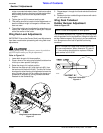
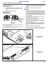
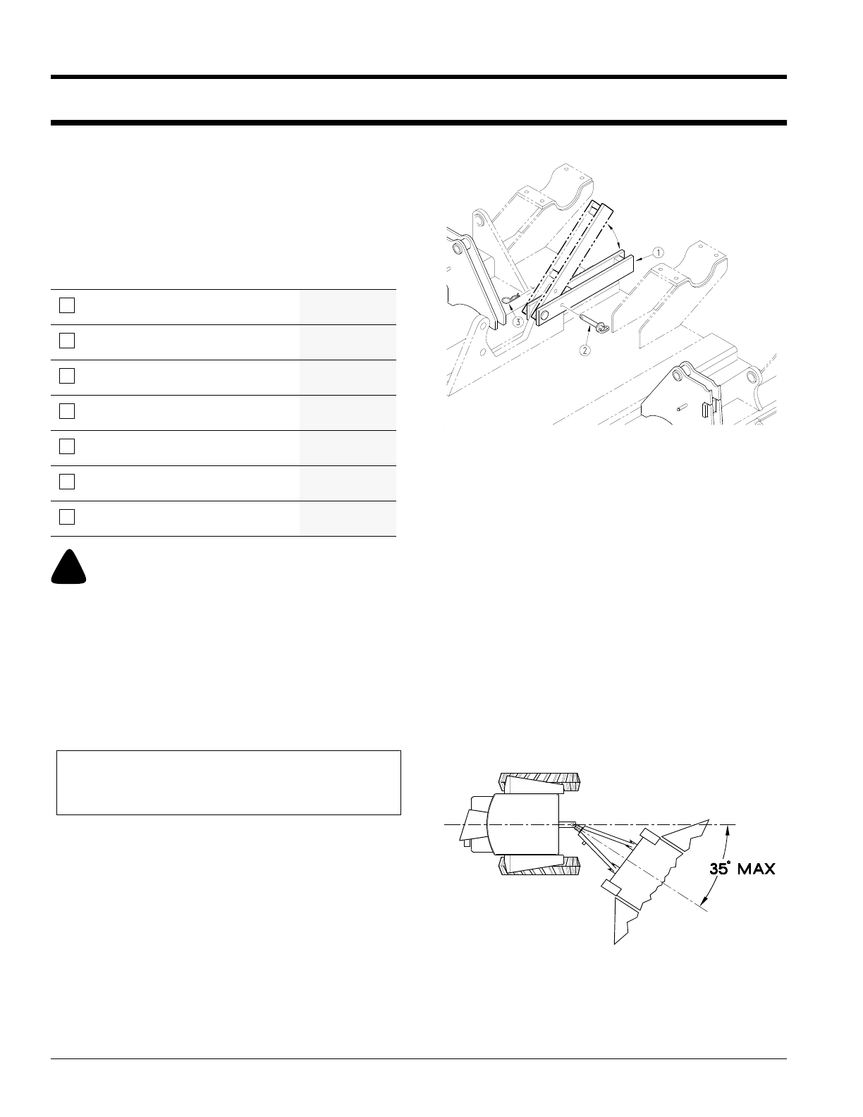
Refer to Figure 2-2:
Optimum Ground speed depends on the density of the
material being cut, the horsepower rating of the tractor,
and (in some cases) terrain.
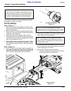
If the cutter-to-tractor PTO is a standard conventional
shaft, avoid tractor-to-cutter turning angles exceeding 35˚.
If equipped with a Constant Velocity PTO shaft, the turn-
ing angle may be increased to 80˚. These extreme angles
are intended for intermittent usage only and not prolong
usage. Plan your field cutting to minimize the number of
turns as well as the extreme angles where turns are
necessary.
Transport Link
Figure 2-1
13885
Conventional U-Joint PTO
Figure 2-2
11934