


8
Section 1 Assembly and Setup
RC45180 & RCM45180 Rotary Cutter 312-382M 7/14/08
Land Pride
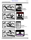
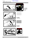
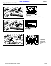
Table of Contents
Section 1 Assembly and Setup
Tractor Requirements
This cutter is designed for tractors with a minimum PTO
horsepower rating of 50 HP and maximum of 150 HP.
!
CAUTION!
Do not over speed PTO or machine damage may result. This
cutter is designed to be used with a tractor using a 540 or
1,000 rpm rear PTO but not both.
Specifically, each cutter is equipped for only one mode of
operation. Do not attempt to operate a 540 PTO cutter
with a 1,000 RPM PTO tractor. Do not operate a 1000
RPM PTO cutter with a 540 PTO tractor. Note that many
tractors provide both 540 and 1,000 RPM PTO modes.
Check your tractors manual to determine your exact con-
figuration.
Before You Start
Read and understand the owners manual for your cutter. A
basic understanding of how it works will aid in the assem-
bly and setup of your cutter.
Before attempting to assemble the cutter use the following
as a check list. Having all the needed parts and equipment
readily at hand will speed up your assembly task and will
make the job as safe as possible.
❑ Check for fasteners and pins that were shipped with the
cutter. Note: All hardware coming from the factory has
been installed in the location where it will be used. If a part
or fastener is temporarily removed for assembly reasons,
remember where it goes. Keep the parts separated.
❑ If a pin, bolt or other part has been removed, and you
are unsure where it is used, use the parts section to iden-
tify it. Be sure the part gets used in the correct location. By
double checking while you assemble, you will decrease
the chance of using a bolt incorrectly that may be needed
later.
❑ Have a fork lift or loader along with chains and safety
stands that are sized for the job ready for the assembly
task.
❑ Have a minimum of 2 people at hand while assembling
the cutter.
❑ Check to see all nuts are tightened. See “Torque Val-
ues Chart” page 24 for additional torque specifications.
Dealer Cutter
Assembly & Preparations
This cutter has been partially assembled at the factory.
The hitch & both wing axles will need to be assembled.
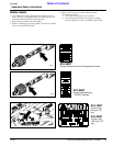
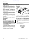
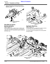
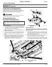
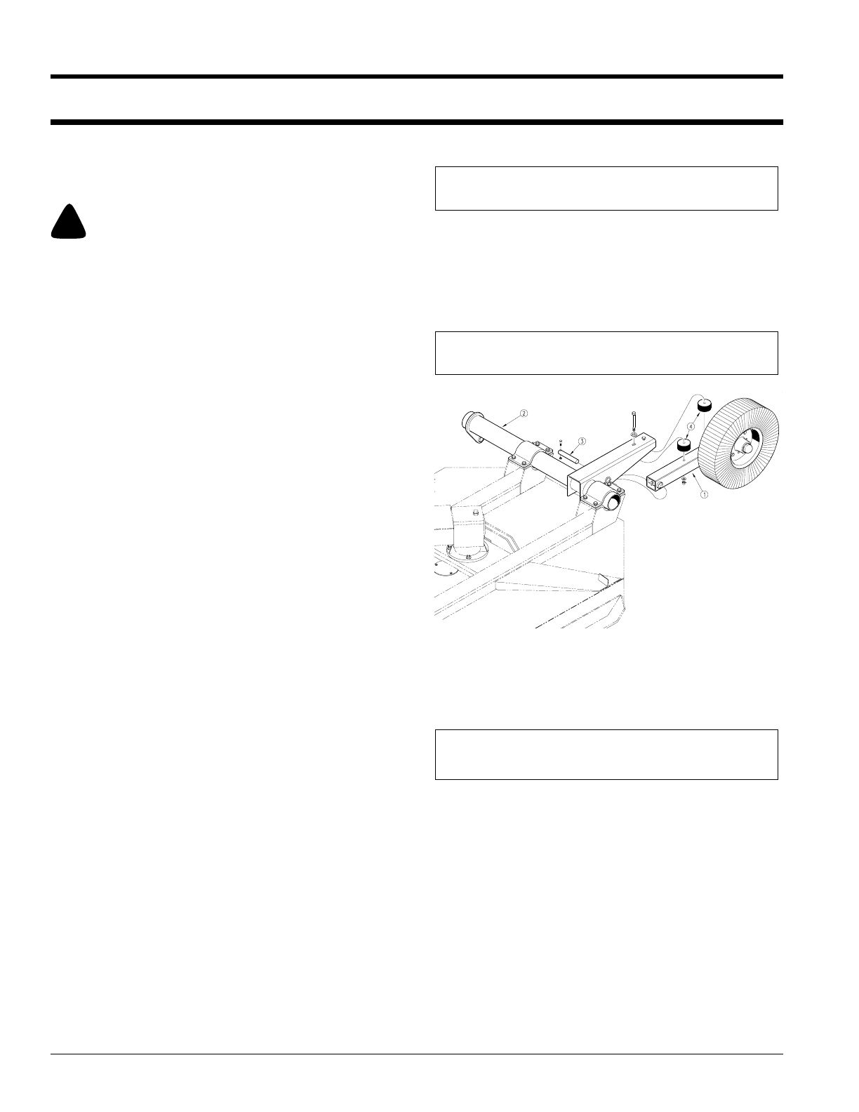
Left & Right Wing Axle Assembly
Refer to Figure 1-1:
1. Assemble axle tube arm assembly (#1) with tire to
wing axle (#2), using axle mount pin (#3) with hard-
ware. Install rubber bumpers (#4) with hardware.
2. Grease points marked by arrows as noted in "Main
tenance & Lubrication" section page 19.
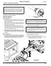
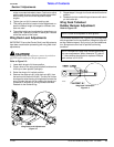
Hitch Assembly
Refer to Figure 1-2:
1. Insert main hitch rear mount bushings (#2) into hitch
pivot. Install the main hitch (#1) to the forward hitch
plates. Secure with 1" x 8" hex bolt (#3) and 1" flat
washers and Nylock nut. Nut should be located to-
ward the inside as shown.
2. Install both leveling rods (#4) through the respective
trunnion pivot of the hitch. Secure the leveling rod to
the hitch with the leveling tube weldment (#6) and a 7/
8" hex nut (#8). Note: The leveling tube weldment
should be screwed onto the leveling rod about 3" as a
preliminary adjustment. Final adjustment should not
be made until the cutter is attached to the tractor.
NOTE: Hardware bag should be banded to unit.
NOTE: Make sure nuts & bolts are tight.
Wing Axle Assembly
Figure 1-1
13869
NOTE: Do not tighten hardware until assembly is
complete.