


16
Section 1 Assembly and Set-Up
10/28/05
Land Pride
Table of Contents
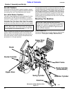
Optional Equipment Assemblies
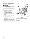
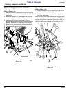
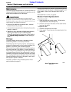
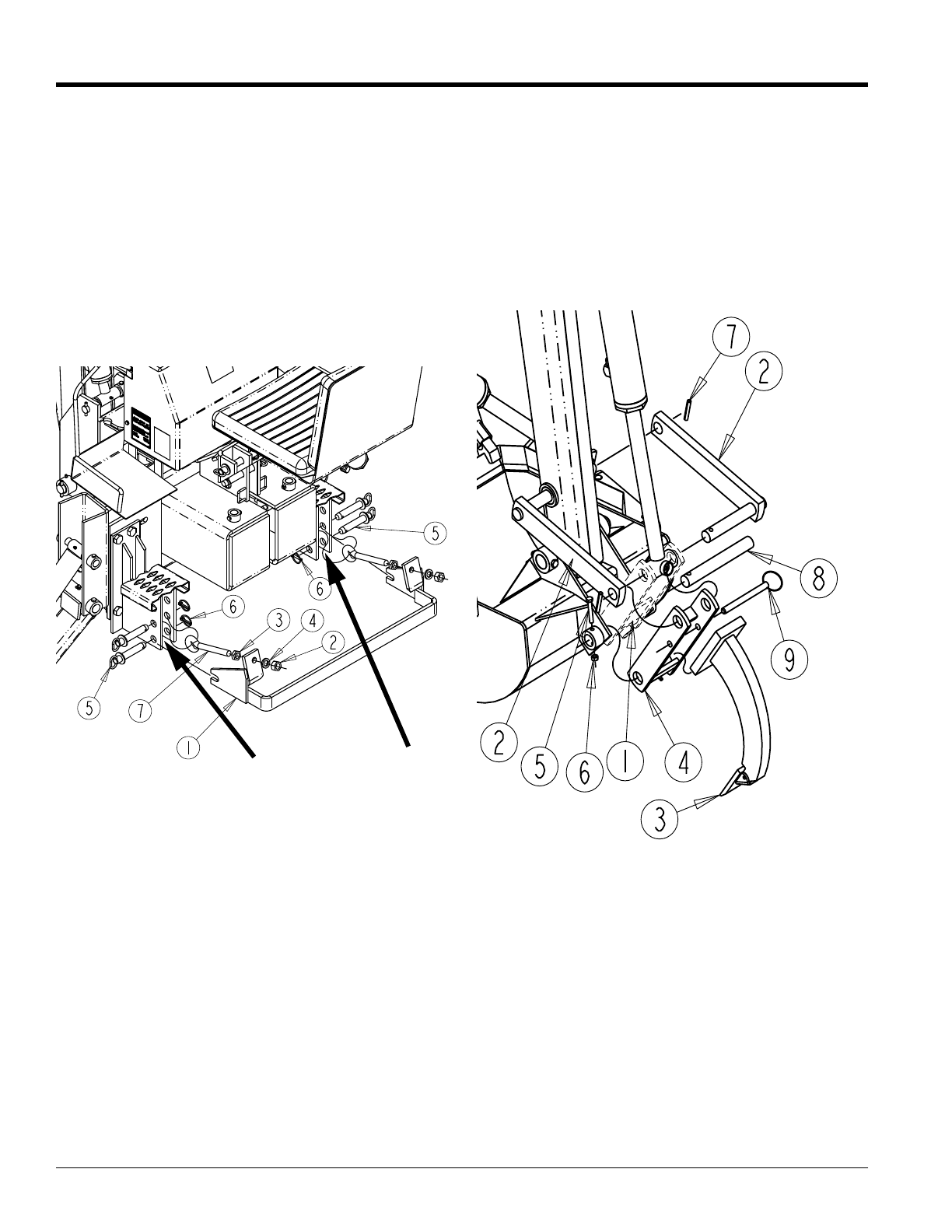
Locking Bar
Refer to Figure 1-13:
1. After the backhoe is attached to the tractor in working
position proceed with the following steps to install the
locking bar.
2. Assemble eyebolts (#7), lockwashers (#4) and nuts
(#2) as shown. Do not tighten.
3. Install pins (#5) through eyebolts (#7) with the
eyebolts being located the inside of backhoe lower link
brackets. Secure pins in place with lynch pins(#6).
4. Adjust the 3/4” bolt against the tractor drawbar link.
5. Tighten eyebolts with nut and jam nut.
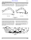
Locking Bar Assembly
Figure 1-13
20598
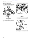
Tractor’s Lower 3-point
mounts here
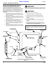
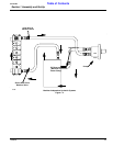
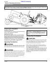
Ripper Tooth
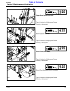
Refer to Figure 1-14:
1. Remove bucket link (#1) by removing pin (#8) and roll
pin (#7) and sliding out links (#2).
2. Assemble ripper tooth assembly with pins and links
from step 1 as shown.
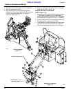
When the ripper tooth is not needed, the complete ripper
assembly does not need to be disassembled. Remove
pin (#9) and slide the ripper tooth (#3) out and store pin
(#9) back in it’s previous location. The ripper tooth link
(#4) can now be used in place of the bucket link (#1).
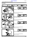
Ripper Tooth Assembly
Figure 1-14