


14
Section 1 Assembly and Set-Up
10/28/05
Land Pride
Table of Contents
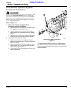
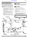
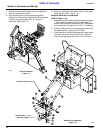
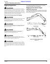
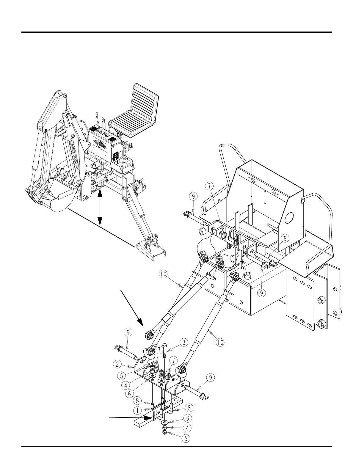
Stabilizer Kit Installation
Figure 1-10
To tractor upper 3-point
No more than 1” from
draw bar support
20571
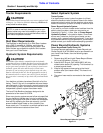
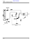
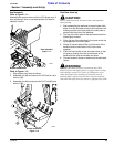
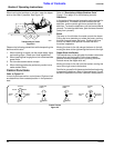
7. Extend boom and lower dipper stick and stabilizers
until they contact the ground.
8. By manipulating the cylinder and placing down
pressure on the boom and stabilizers, lift the backhoe
vertically to approximately 8” to 12” of ground
clearance. See Figure 1-9.
8” to 12”
Ground Clearance
Figure 1-9
20565
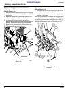
9. Attach the backhoe to the lower lift arms of the tractor
using the pins (#7) in Figure 1-8.
Backhoe Stabilizer Kit Installation
Refer to Figure 1-10:
1. Assemble drawbar bracket (#2) to the tractor drawbar
1” from drawbar support with 5/8” U-bolts (#8) flat
washers (#6) nuts (#4) and jamnuts (#5). The spacers
(#1) may have to be used on 2” and 2 1/4” drawbars.
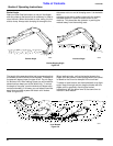
2. Insert bolt (#3) (drill 5/8” hole if necessary) secure with
flat washer (#6) nut (#4) and jam nut (#5).
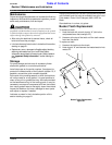
3. Install stabilizer links (#10) as shown and insert clevis
pins (#9) and secure with linchpins (#7). Stabilizer
links can be adjusted at both ends to fit your tractor.