


Drawbar and PTO
PY80265,05GO863 –19–10SEP05–1/1
Attaching PTO-Driven Implement
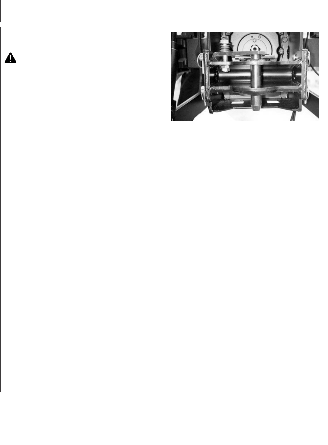
PY1094 –UN–10APR05
A—Drawbar
CAUTION: Stop engine before attaching
implement or working in area of implement
hitch.
1. Attach implement to tractor before connecting PTO
drive line. Raise hitch to upward position if it is not to
be used.
2. Range shift lever in neutral (N), key to OFF position to
stop engine and set brakes.
3. If PTO driven implement will be attached to drawbar
(A), the drawbar must be positioned so there is 355
mm (14 in.) between end of PTO shaft and center of
drawbar pin hole. Make sure drawbar locking pins and
spring pins are in place. If implement will be connected
to 3-Point Hitch, be sure drawbar will not interfere.
Remove it if necessary.
NOTE: There are two holes at the front of the drawbar.
Place the drawbar pin in the second hole for the
proper 355 mm (14 in.) length.
4. Rotate PTO shield upward for clearance. With engine
off, turn shaft slightly by hand if necessary to line up
splines. Connect drive line to PTO shaft. Pull out on
shaft to be sure drive line is locked to PTO shaft. Place
PTO shield in downward position.
5. Be sure all shields are in place and in good condition.
Never operate PTO unless master shield is properly
installed. WITH ENGINE STOPPED, check integral
shields on drive line by making sure they rotate freely
on shaft. Lubricate or repair as necessary.
6. Check carefully for any interference, make sure hitch is
raised to the upper position if it is not used.
65-2
022607
PN=67